Annotations
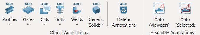
The Annotations toolbar are shown as below :
- Place the mouse cursor over the icon to expose the Tooltip which will contain detail instruction on how to use the function.
- Right-click on the icon to expose the settings dialog before using it.
 Profile Annotation / Frame Annotation
Profile Annotation is used to annotate elements such as beam, column, brace, purlins and girts.
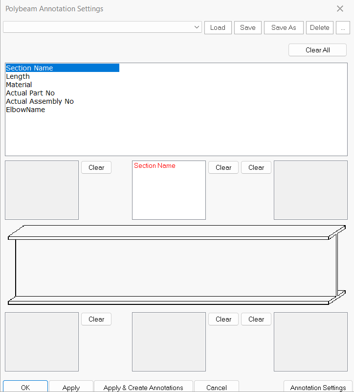
Click on the pull down of Profile Annotation icon to find Annotation Settings (as shown below)
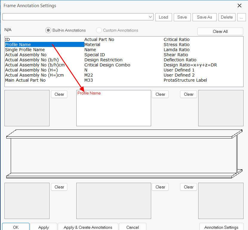
The various type of annotations are listed in the top table :
- Click & drag any annotation name into the box which also defines the position of the annotation
- In the example above, the Profiles & Material is added into the top middle box
- In the example above, the Profiles & Material is added into the top middle box
- OK : Save and exit the dialog
- Apply & Create Annotation : Click this will create the annotations immediately If you have selected any elements before entering this dialog,
- Annotation Settings button (lower right) : Access to Annotation Text Property Edit where you can view or change the text settings :
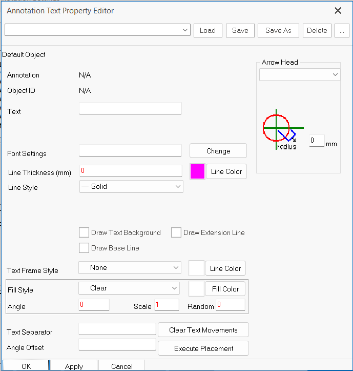
- Font type & size (by clicking the "Change" beside the "Font Settings")
- Format or style of the annotations
- Arrow Heads
- OK to save and exit the dialog
After confirming the Annotations Settings, to create the annotation :
- Select members (s) in the ViewPort
- Left-click on Profile Annotation
 icon
icon
An example of profile annotations added is shown below:

Tip : To easily select only the required elements without accidentally selecting the border of Viewport or other objects :
- Click on Selectability
 icon in the Edit tab to access the Drawing Options dialog
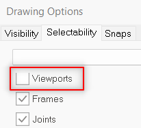
- Untick Viewport > OK
The same options are available in Visibility tab which controls what is shown in the drawing.
Plate Annotation
Plate Annotation is used to annotate steel plates.
Click on the pull down of Plate Annotation icon to find Plate Annotation Settings
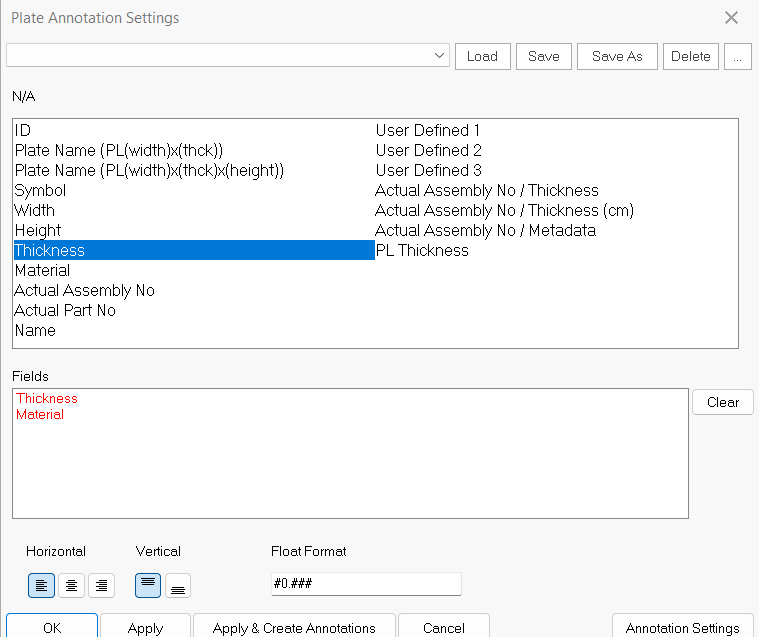
- Click & Drag the required annotation from the top table into the Fields below:
- Example, PL Thickness & Material
- Example, PL Thickness & Material
- Apply & Create Annotation : Click this will create the annotations immediately If you have selected any elements before entering this dialog,
- Annotation Settings button (lower right) : Access to Annotation Text Property Edit where you can view or change the text settings (as outlined in previous section)
- OK to save and exit the dialog
After confirming the Annotations Settings, to create the annotation :
- Select plates (s) in the ViewPort
- Left-click on Plate Profile Annotation icon
 Bolt Annotation
Bolt Annotation is used to annotate bolts.
Click on the pull down of Bolt Annotation icon to find Bolt Annotation Settings (as shown below)
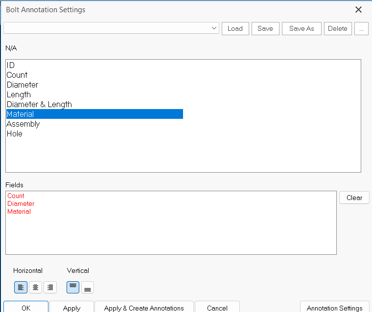
- Click & Drag the required annotation from the top table into the Fields below
- Example, Count, Diameter & Material is included as shown above
- Example, Count, Diameter & Material is included as shown above
- Apply & Create Annotation : Clicking this will create the annotations immediately If you have selected any elements before entering this dialog,
- Annotation Settings button (lower right) : Access to Annotation Text Property Edit where you can view or change the text settings (as outlined in previous section)
- OK to save and exit the dialog
After confirming the Annotations Settings, to create the annotation :
- Select plates (s) in the ViewPort
- Left-click on Bolt Profile Annotation icon
Weld Annotation
- Select welding(s) in the ViewPort
(Either select single welding or highlight multiple weldings) - Left-click on Weld Annotation icon
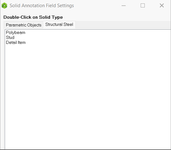
Generic Solid Annotation
Dimension Placement
- Right click to set the Dimension Placement Settings (optional)
- Select dimension(s) in the ViewPort
- Left-click on Dimension Placement icon

Level Indicator Placement
- Select level indicator(s) in the ViewPort
- Left-click on Level Indicator Placement icon

Weld Annotation (Single Weld)
- Select welding in the ViewPort
- Left-click on Weld Annotation icon

- Left-click on the welding again to allocate the head of arrow.
- Drag to a preferred location and left-click with "ALT" to place the annotation.
Assembly Annotation Auto (Viewport) 
- Select the ViewPort
- Left-click on Auto (Viewport) icon
Assembly Annotation Auto (Selected) 
(This is similar to "Profile Annotation". The different is that this feature can annotate elements such as plate.)
- Select member(s) in the ViewPort
(Either select single members, or highlight multiple members) - Left-click on Auto (selected) icon