Assembly and part drawings are created automatically in ProtaSteel.
These drawings are prepared with the settings specified by the software. These
settings can be customized by user.
- Changing the
Drawing Properties
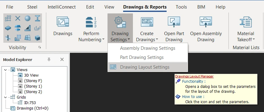
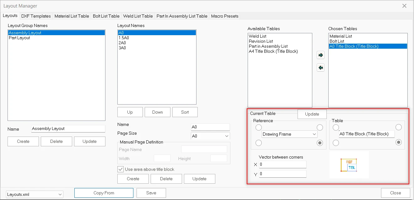
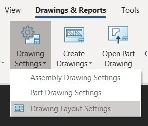
Open the “Drawing Settings” from the “Drawing and Reports”
top menu and choose "Drawing Layout Settings" to change the drawing layout properties.
In the “Layout” tab, new names can be created in the “Layout
Group Names”. Press “Create” button
to add a new layout size. Layout names
include the paper size which will use in “Assembly/Part Drawing Macro”.
“Available Tables” tab has 4 parameters to add drawings.
Which parameter want to use in drawing, it can move to “Chosen Table”.
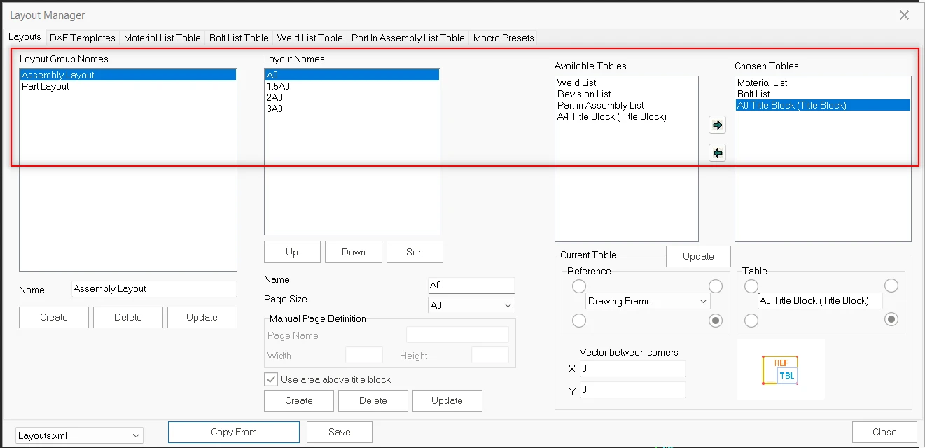
Current table can be located using a reference in the drawing. So, chosen
tables are located in the drawing according to this rule.
- Select a parameter in the “Chosen Tables”
- Set the location of the parameter using reference and table in the “Current Table”
- Click to “Update” button.
- Click to “Save” and “Close” button.
When A0 paper size is selected for assembly
drawings, it will be prepared according to this settings.
The other paper sizes can be similarly customized. ProtaSteel considers the
default settings for the other drawings.
- Changing of The Assembly Drawing Properties
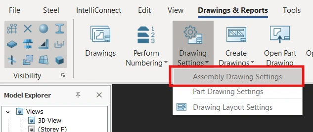
Click on the menu item “Drawings and Report” >
“Drawings Settings" > “Assembly Drawing Settings”
In the “Assembly Drawing Macro”, settings for different profile
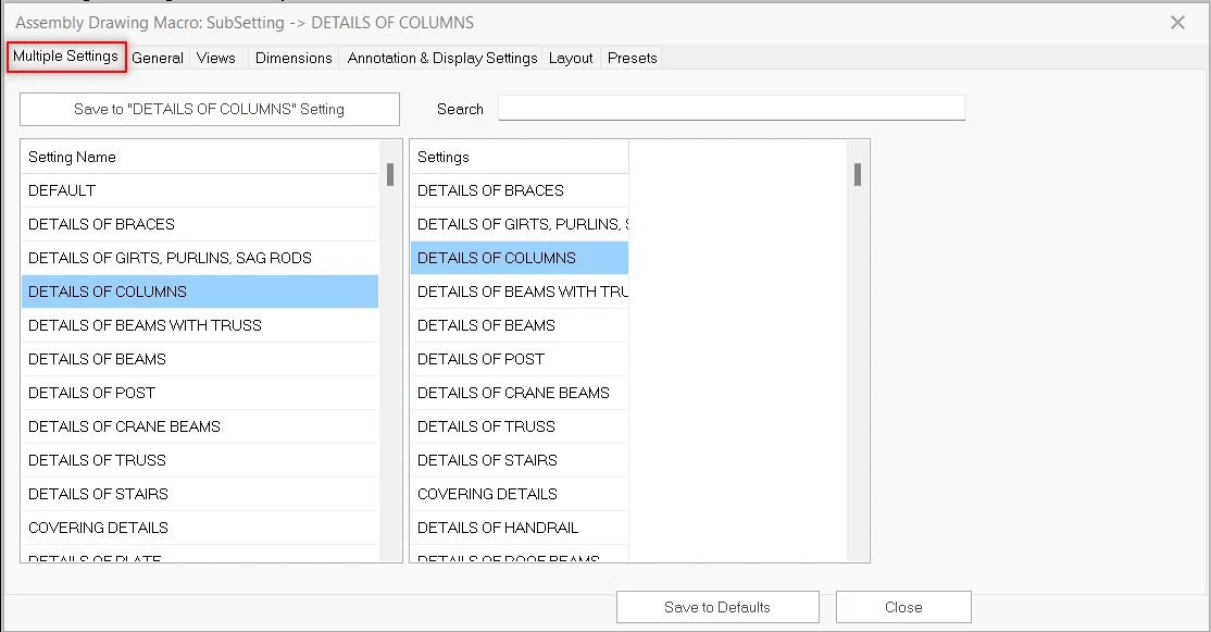
groups can be stored. There are different settings for each structural members in the “Multiple
Settings” tab. For example, settings group of the column drawings and
settings group of the roof beam drawings can be saved separately. This distinction
can be understandable with prefix. Settings on the right table directed
according to assembly prefix names. The settings on the right table is
redirected to a setting group according to prefix of the assembly drawing. The
table on the left is contains the drawing settings. For example, assembly names
which started with CL, will be drawing with selected the “Details of
Columns”.
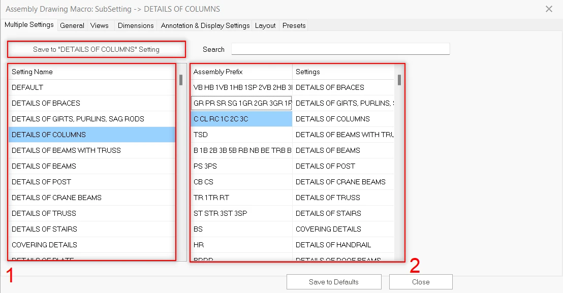
- Order of the Application:
· Select an object group from the
“Setting Name”. For example “Details
of Columns”.
· Drawing title, Drawing name prefix, page size,
scale of the drawing etc. can be changed in the “General” tab. Additionally,
can also select the include single parts, draw single assembly in each draw,
freeze drawings.

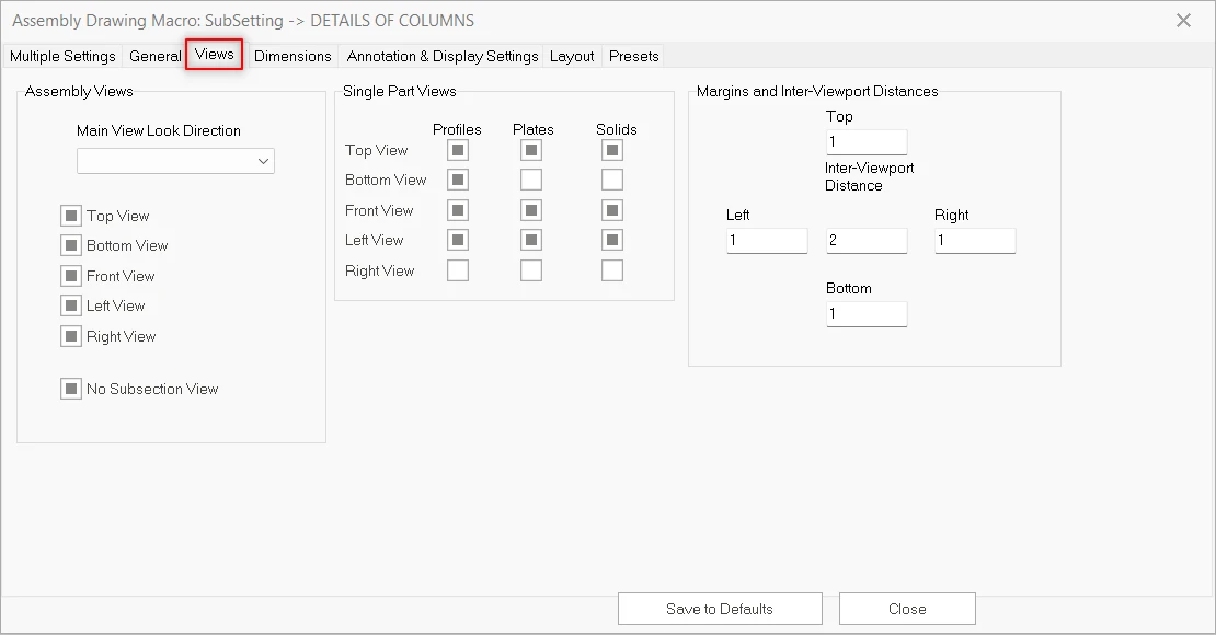
· Assembly views, single part views and viewport
distances can be set on the “Views” tab.
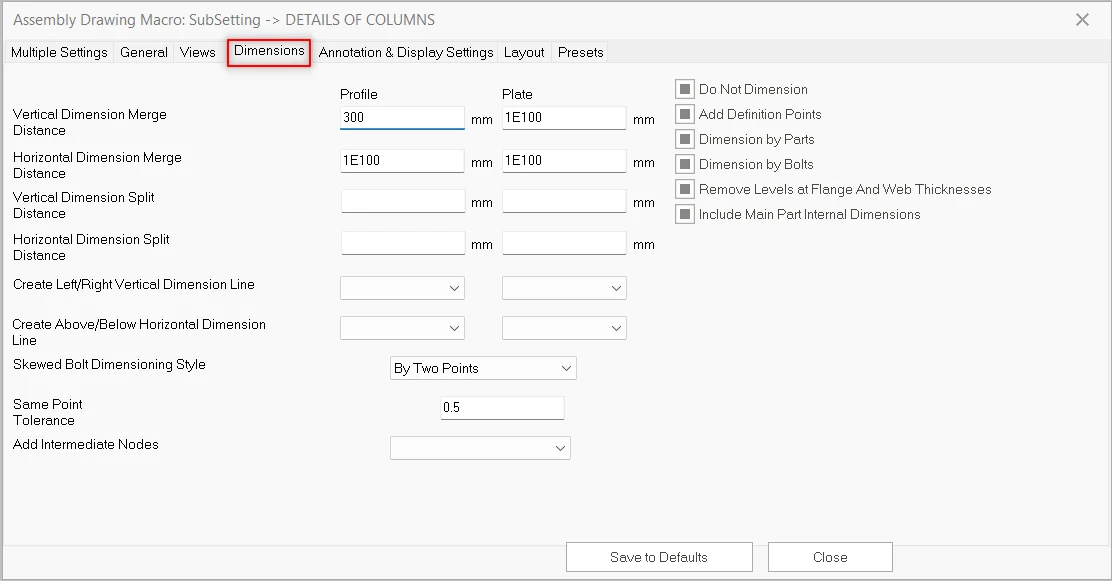
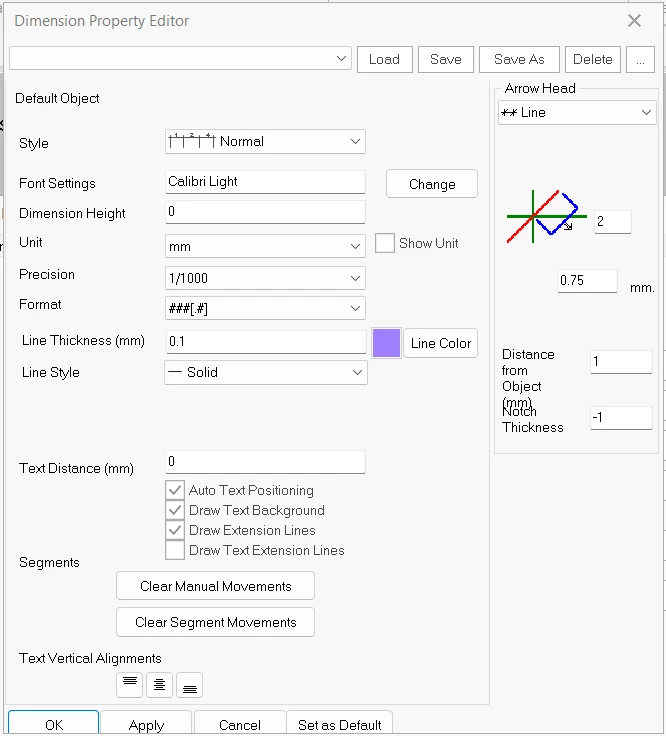
“Dimensions” tab.
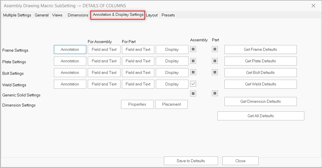
changed on the “Annotation and
Display Settings” tab. For example, frame properties or dimension
properties.
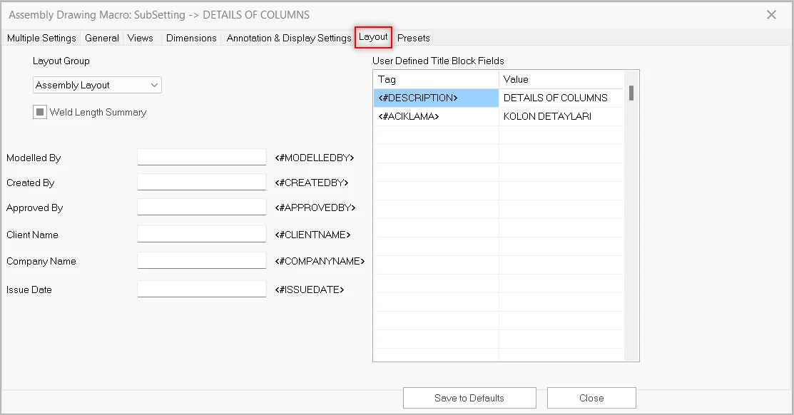
the “layout” tab.
title block information. “Assembly Layout” will used in this
drawing. You can find assembly
layout settings in the “Drawings Layout Manager”.
settings will be use as company standard in the all projects.
other structural members in the “Multiple Settings” tab.
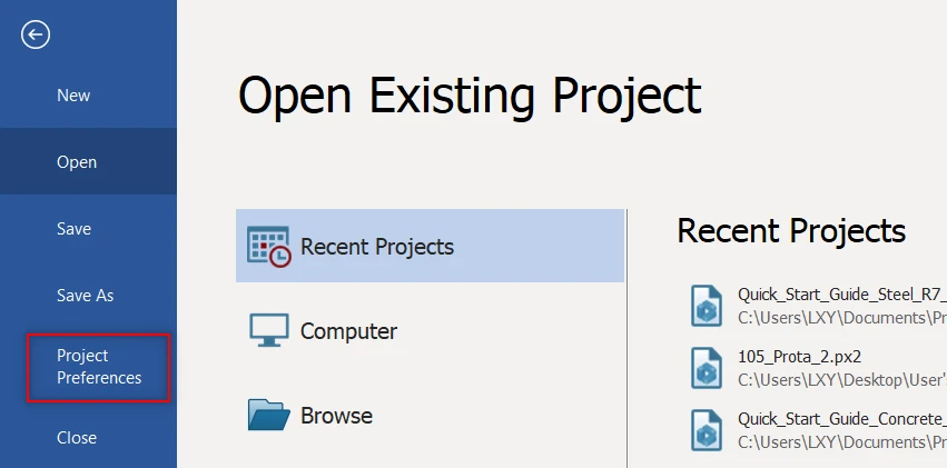
saved in “Project Preferences” file. Please save as this file before
start to changing. If you want to back ProtaSteel default settings or if you experience the corrupted problem in the future, you can replace the settings.
How can I open
the Project Preferences File?
Customize Layout/Sheet/Titleblock in Assembly and Part Drawings
- Go to Drawings & Reports > Drawings Settings > Drawings Layout Settings
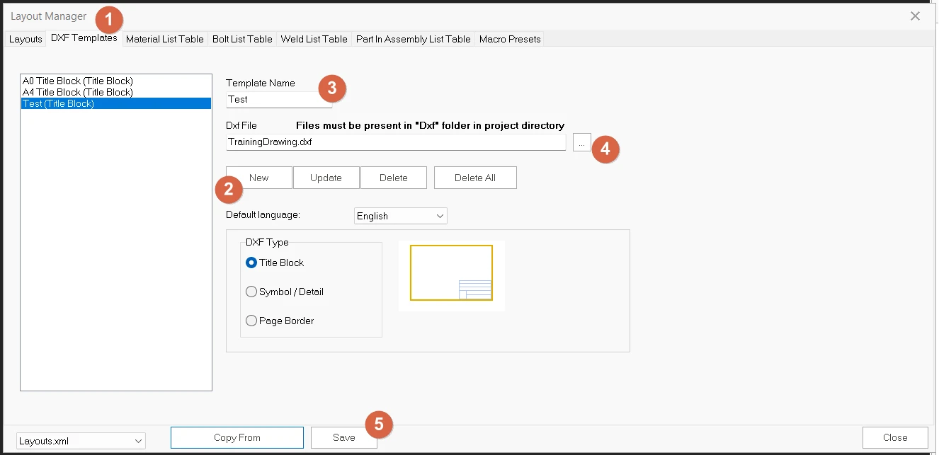
- In the Layout Manager
- Go to DXF Templates tab,
- Click "New" to create new title block.
- Rename the "Template Name" with the "Title Block" Ticked. (In this example, will be using template name as "Test".
- Search for the DXF directory
- Save the name.
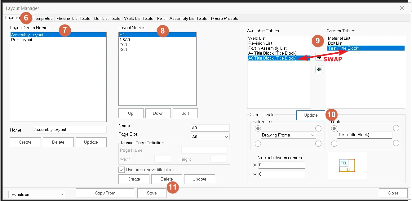
- Switch to Layout tab
- Select either Assembly Layout or Part Layout. In this example, I will show you Assembly Layout.
- Select the Layout Name A0 (for A0 size)
- Under the available tables, make sure the titleBlock moved into "Chosen Tables" by replacing the current "A0 Title Block" or “A4 Title Block".
- Click "Update" the Table (Repeat this to "Part Layout" if you wish to apply the same titleblock to Part Layout as well)
- Save the Layout Manager and close.
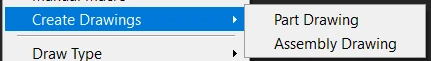
- Lastly, highlight the Part elements or assembly elements that wish to be generated into the drawing and right click to "Create Drawings" for either Part Drawing or Assembly Drawing.