

"Load Combinations"
button which is located on the Pre-Analysis tab of the Building Analysis form. The figure below shows the Load Combination Editor Tab.
P-Delta Analysis
Scope & Limitations
ProtaStructure P-delta analysis is based on “Two cycle iterative Method” (Chen and Lui 1991). This method utilizes geometric stiffness matrix in the computation. It takes into account the compression softening or tension stiffening due to axial loads on the members (geometric stiffness matrix) :
- Firstly, the geometric stiffness matrix is calculated (by iteration) for G, Q, QP1 (Pattern1), QP2 (Pattern2), G+Q
- For design load cases, [Ke + Kg] is used to incorporate second order effects.
- For example, for G+Q+E (Earthquake) combination : G, Q are solved using [Ke + Kg (G,Q)] and E loadcases are solved using [Ke + Kg (G+Q)].
This method only takes into account P-Small Delta, not the P-Big Delta. The second-order effects are calculated based on the deflected shape and no additional imperfections are considered. Hence, the additional moments calculated from P-Small Delta analysis is usually small, especially for braced concrete building. If the structure is sway-sensitive or slender, then a nonlinear second-order P-Large Delta analysis is required (out of scope currently).
For more details regarding second order effect, please refer to
Sway Sensitivity & Second-Order Effects
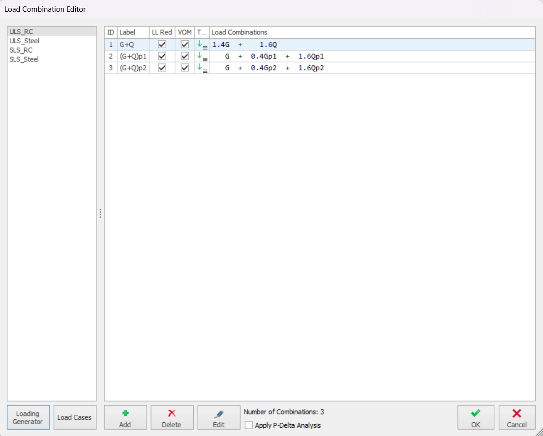
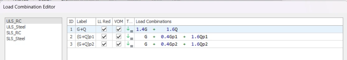
Load Combinations Editor
“Load Combinations Editor” lists the current set of load combinations. A typical combination set is given below:
“
Add” button, a copy of that combination will be created. By using the related cells in the table, you can modify load factors and combination names.
“Delete” button.
Finite Elements Floor Analysis
module are obtained from the first combination in the table. The first combination should therefore include unpattern
Dead Load (G) and
Imposed Live Load (Q).
1.4G.
LL. Red cell. Click in this cell to toggle the setting as required.
"Loading Generator" button.
Designating Vertical-Only Load Combinations
Designating
selected members as “Vertical-Only (VOM)” is not sufficient. Idea behind this
feature is designing vertical-only members only for non-seismic combinations,
whereas the rest of the structure is designed for all combinations.
By default,
ProtaStructure will designate only the gravity combinations as ‘vertical-only’.
This means that the members designated as ‘vertical-only’ will only use these
combinations in design. You can set any combination as vertical-only by
checking the VOM option next to a combination in the load combination editor.
Loading Generator
“Loading Generator” is used to automatically create a new set of load combinations within the Load Combinations Editor.
"Vertical Loads combinations"
tab is used to define the basic gravity combinations and
Patterned gravity combinations. It is also where
Staged Construction combinations are defined.
"Horizontal Loads combinations" tab is used to define
Seismic, Notional Loading, Wind Loading, and Soil Pressure.
Temperature Loading.
Vertical Loads
“Define Dead Loads (G)” and
“Define Live Loads (Q)“ to create the first combination as all spans fully loaded with max. factored G and Q.
Max. G Factor and
Max. Q Factor fields.
psi-zero factor is only displayed if the project design code is EC2. The default for
psi-zero is 0.7. This factor is applied to Q in those combinations in which the imposed load is considered as an accompanying action.
“Create Unfactored G+Q Combination” to include an additional combination of
1.0G + 1.0Q.
Check
“Define Pattern Loads Automatically” to activate the pattern load template from which five basic pattern load arrangements (referred to as P1, P2, P3, P4 and P5) can be selected :
The current design code controls which load case(s) are patterned:
- BS8110 /CP65 – both G and Q are patterned.
- EC 2 – only Q is patterned
“Direction Dependent Pattern Loading” option to enable the patterns to be applied in one direction only.
each direction dependent pattern are shown below:
Staged Construction
“Stage Construction Cases” to enable a staged construction analysis.
“Stage Duration” field is used to specify the default duration of each stage, this can subsequently be amended for individual stages.
“Stage Construction Cases: G” to create an S
G staged load case.
“Stage Construction Cases: Q” to create an S
Q staged load case.
“Create New Combinations for Staged G and Q” to create two sets of combinations, one with the unstaged cases and the second with the staged cases. When not checked, only one set of combinations is created which uses the staged cases.
duration of the stages via the
“Load Cases” button >
Load Case Editor.
Lateral Loads
“Wind Loads” and
“Soil Pressure” type lateral load cases can be specified in the
"Horizontal Load Combinations".
Seismic Loads
"Horizontal Load combinations" tab.
"Equivalent Static Load" and
"Modal Response Spectrum".
"Modal Response Spectrum" shall be selected for irregular building model in either plan or elevation while
"Equivalent Static Load" option shall only be select for a simpler model.
- The "Load cases" of the "Modal Response Spectrum" are defined as Sx+, Sx-, Sy+, Sy- while the load cases of "Equivalent Static Load" are defined as Ex+, Ex-, Ey+, Ey-.
- Additional "Load Combinations" can be generated if the "Create All Possible Combinations for symmetric results" option is checked. This option is used to cater for additional load combinations in the same directions but in negative sign.
Temperature Loading
“Temperature Loading” to create combinations which include a thermal load case.
Manual Definition of Load Cases
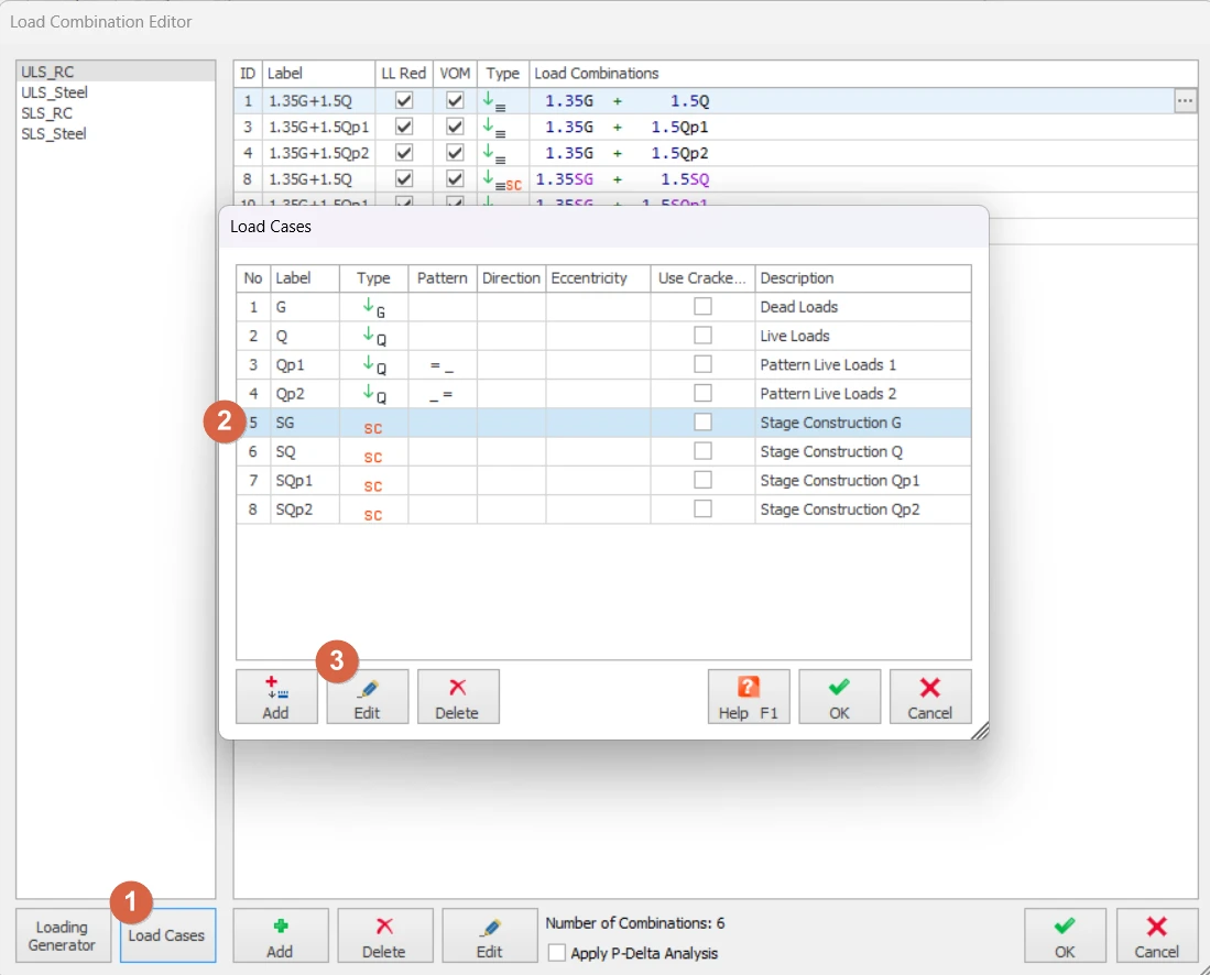
“Load Combinations Editor" is displayed you can click the
“Load Cases”
button in order to see a table of all the load cases in the load combination set.

- The second column in the table contains the label of the load case. Any string value can be assigned as the label but short names are preferable.
- The third column graphically explains the load case type by the use of a symbol.
- The forth column defines the pattern of the vertical load case ( _ empty, = full ).
- The fifth column shows the direction of the lateral load cases, whereas sixth column specifies the eccentricity (if any) of the lateral load case.
- The seventh column is allow users to check the option "Use Cracked Section". The stiffness table will only be applied for load cases with this option checked, except for seismic load cases where cracked sections are always assumed.
- The last column includes the definition of the load case. Always give a brief explanatory description to the load cases that you create.
“Add Below” or
“Add Above”
buttons. After the load case is added, press the
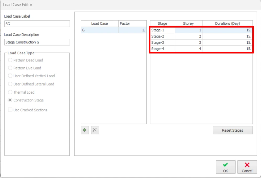
“Edit” button to modify it using the
“Load Case Editor”.
“Load Case Label” and
“Load Case Description” fields must be filled with brief explanations.
Vertical Loads
direction-dependent pattern load cases can be defined (while beams in one direction have pattern loading, other direction beams are fully loaded or unloaded according to load transfer mechanism). In this way, the reduction of the axial load in the columns is minimized.
“Vertical Load” option on the
“Load Case Type” frame, three load case types will be activated in the list on the right.
- “User Defined Vertical Load” allows you to define manual vertical loads other than the dead and live load category. These loads can be assigned onto beams, slabs and column/wall nodes.
- “Dead Load Case” generally consists of member self weights and additional dead loads. However, you are free to assign additional distributed loads or point loads under the dead load case category.
- “Live Load Case” includes vertical temporary imposed loads on the building other than dead load and other stationary loads.
- "Roof Live Load Case" consists of the live loading acting on the roof.
- "Snow Load Case" and "Rain Load Case" includes the forces/ weight of the snow or rain when it is falling on the structural members.
- "Vertical Earthquake Load Case" considers the vertical forces that is induced by the earthquake.
“Load Pattern” field under the list on the right.
‘1’, and unloaded spans as
‘0’. Leave this field blank for cases that all spans are loaded.
“Full-Empty-Full-Full-Empty” pattern, enter 10110 in this field. If all spans will be fully loaded, then leave this field empty.
“Pattern Direction” field will be activated. Pattern load will be applied along the direction specified here.
“Dir-1”
beams.
“None” to apply the pattern loading to both direction beams.
Lateral Loads
“User Defined Lateral Loads”,
“Notional Loads”, "Notional Load Case", "Equivalent Static Earthquake Load", "Earthquake Spectrum Loading" or
“Wind Load”
.
“User-defined Lateral Load” or
“Wind Load” from the list. Application points and magnitudes can then be entered in
“Winds and Storey Loads”.
“Notional Load”, lateral loads are automatically calculated as a percentage of the storey weight and cannot be modified.
“Lateral Loading” tab of Project Parameters in the Pre-Analysis.
“Loading Direction” is said to be
“Primary” for the angle value specified in
“Building Parameters”. The
“Secondary (Primary + 90)” direction is perpendicular to the primary direction.
“Primary”. For a Y direction loading select
“Secondary (Primary+90)”.
“Eccentricity” field. For each direction, eccentricity can be specified as
“+” or
“-“. The amount of eccentricity can be controlled globally from
“Building Parameters”. The default value for eccentricity is
5%.
Thermal Load
“Thermal Load” option on the
“Load Case Type” frame, then simply fill in the
“Load Case Label” and
“Load Case Description” fields.
Adjusting Construction Stage Content and Duration
“Loading Generator" to define your staged construction load cases, you can then click the
“Load Cases” button in order adjust the content and duration of each stage.
“Edit” button to modify it using the
“Load Case Editor”.
Adjusting Construction Stage Content
increase the number of storeys considered in a stage – simply change the storey number at which the next stage commences.