Seismic Analysis To Eurocode 8
ProtaStructure can now calculate seismic loads in accordance EuroCode 8. Country specific requirements of the following National Annex have been implemented :
- MS EN 1998-1 : 2015 (Malaysia National Annex)
- SS EN 1998-1 : 2013 (Singapore National Annex)
Go to Building Analysis dialog > Pre-analysis tab :
- Click on Settings Center > Code section will be shown > Pick Earthquake Code
- Click Seismic Parameter to access the Seismic Parameters & Settings
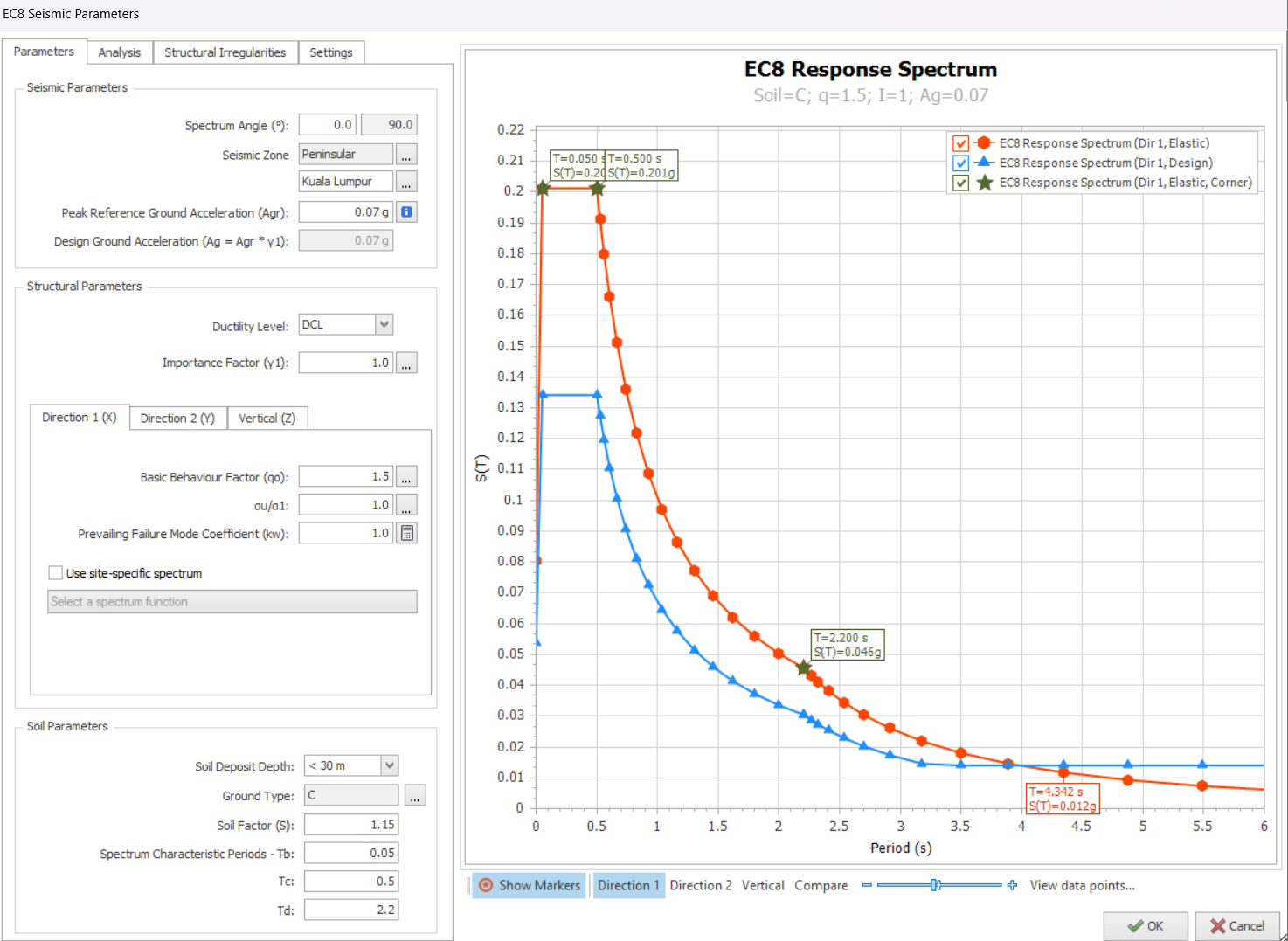
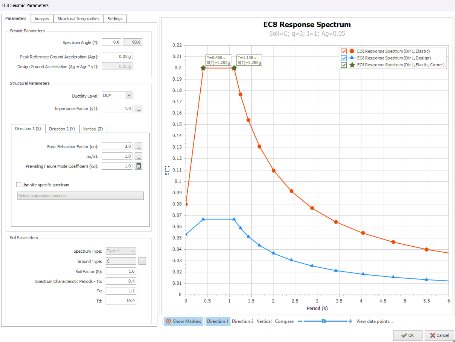
Malaysia NA
Singapore NA

Click the
i icon for more information and guidance on the parameter.
i icon for more information and guidance on the parameter.
Parameters
The following are explanation of key inputs in “Parameters” tab :
- Spectrum Angle : Is the angle of the applied seismic forces with respect to the orientation of the structure on plan view; measured anti-clockwise from global horizontal. For example, if a rectangular building is modelled at a rotated angle, then the spectrum angle should be changed accordingly.
- Seismic Zone :
- Singapore NA : Not applicable & hence hidden
- Malaysia NA : User to select Zone and City or Town > Agr will automatically update.
- Peak Reference Ground Acceleration (Agr) : Default values according to NA or City selected. This value can be changed.
- Ductility Level : DCL / DCM / DCH > User to choose (for low seismic zone, choose DCL)
- Importance Factor : User to select
- Behavior Factor (q) and Overstrength Factor (αu/α1) are automatically fetched from tables in the seismic code.
- Prevailing Failure Mode Coefficient (kw) : Factor associated with the prevailing failure mode in structural system with walls. Automatically fixed according to NA chosen.
- Soil Parameters : Options available will depend on NA chosen.
- Soil Deposit Depth (applicable only to Malaysia NA) : User to choose
- Ground Type : User to select and all other fields, example Tb, Tc, & Td will be automatically updated.
Ductility Level
EC8 stipulates upper limits of axial compression ratios (normalised axial force) for ductile walls & columns for DCM and DCH, but no restriction for DCL.
For example, in the ductile design of shear walls in DCM and DCH, according to EN 1998-1:2004, Clause 5.4.3.4.1(2) for DCM and Clause 5.5.3.4.1(2) for DCH, the normalized design axial force shall not exceed a specified percentage of the theoretical axial concrete capacity (excluding reinforcement), as shown below:
This means that only 35% (DCH) & 40% (DCM) axial capacity of the shear walls can be utilized based on concrete area only, ignoring any reinforcement.
For columns, the axial load ratio limits are 0.65 for DCM and 0.55 for DCH, as specified in EN 1998-1:2004, Clause 5.4.3.2.1(3) for DCM and 5.5.3.2.1(3) for DCH.
This directly results in
DCL being the most practical and efficient design choice for low seismic zones :
DCL being the most practical and efficient design choice for low seismic zones :
- EuroCode 8 does not specify an upper PGA (Peak Ground Acceleration) limit for use of DCM, rather it sets a limit below which seismic design provision can be ignored for low seismicity region, i.e. where DCL can be adopted.
- Cases where ground design acceleration is not greater than 0.10g may be considered as low seismicity, allowing the use of simplified DCL design method.
- The main reason DCL design is more economical for low seismic zone is the reduction in design seismic load allowed for DCM & DCH is too small to compensate for the drastic reduction in the column & wall axial capacity limits.
- Further, for DCM & DCH, there are additional rigorous & onerous design & detailing requirements, e.g. higher minimum steel requirements.
- To summarize, for low seismic zones, DCL is recommended as it is more practical and economical.
Quasi-Permanent Factors
Quasi-permanent load coefficients are implemented for EuroCode are namely:
- Quasi-permanent Coefficient for Live Loads (Ψ2, Q)
- Quasi-permanent Coefficient for Roof Live Loads (Ψ2, Qr)
- Quasi-permanent Coefficient for Snow Loads (Ψ2, Qs)
These factors can be changed in Settings Center > Nationally Determined Parameter (NDP) – a shown below
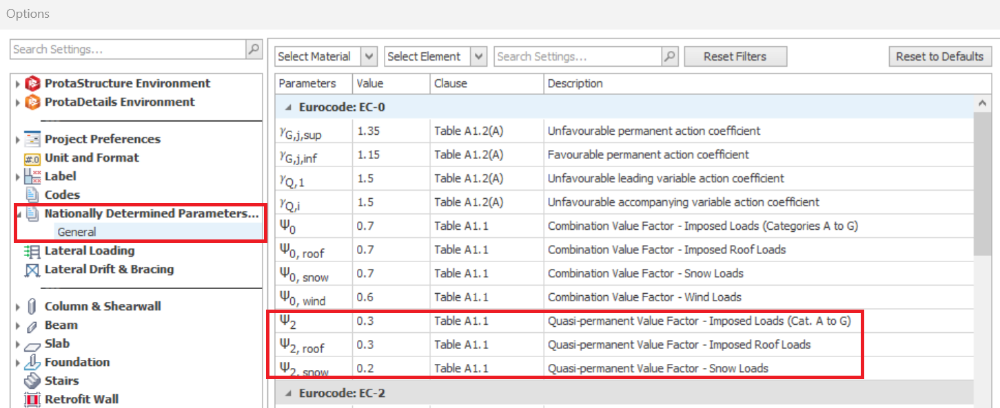
These factors are used for the following purposes in ProtaStructure:
- Calculating the seismic mass to be used in earthquake analysis.
- Creating load combinations for seismic actions.
Seismic Mass Calculation
In the seismic analysis, the mass associated with permanent loads should be combined with that associated with variable loads.
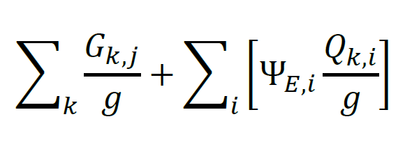
Where:
Gk,j is the
characteristic value of the jth permanent load
characteristic value of the jth permanent load
Qk,i is the characteristic
value of the ith variable load
value of the ith variable load
g is the acceleration due to gravity
ΨE,i is the
mass combination factor for the mass corresponding to the ith
variable action for the seismic
design situation.
mass combination factor for the mass corresponding to the ith
variable action for the seismic
design situation.
For
buildings, ΨE,i is derived from the following relation:
buildings, ΨE,i is derived from the following relation:
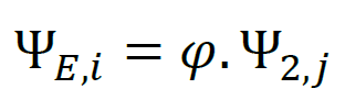
Ψ2,i is associated with the quasi-permanent values
for variable loads, as given in EC0, depending on the categories of loads.
These values are considered automatically by ProtaStructure depending on the
selected Eurocode National Annex.
for variable loads, as given in EC0, depending on the categories of loads.
These values are considered automatically by ProtaStructure depending on the
selected Eurocode National Annex.
φ accounts for the probability of the simultaneous presence of variable loads during the seismic event. These values are again considered automatically by ProtaStructure depending on the selected Eurocode National Annex.
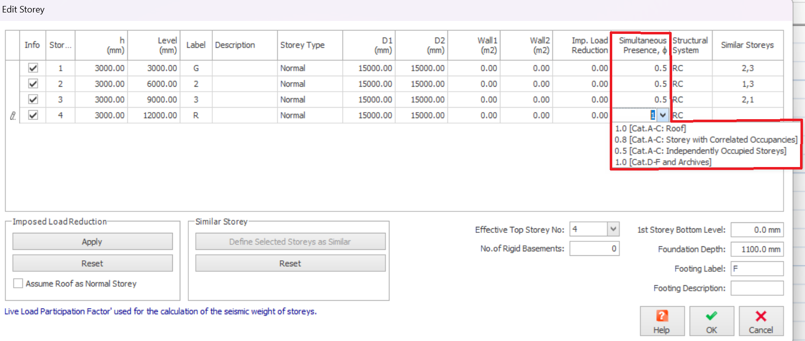
Simultaneous presence factors Φ can be specified for each storey in ProtaStructure using the Edit Storey command (as shown below).
Seismic Combinations
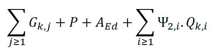
ProtaStructure uses equations 6.10 and 9.10 for ULS combinations. The seismic combinations are generated using the following formula:
Where:
Gk,j is
the permanent loads
the permanent loads
P is the prestressing
action, whenever applicable
action, whenever applicable
AEd is
the design value of the seismic action. AEd includes the importance factor γ1
the design value of the seismic action. AEd includes the importance factor γ1
Ψ2,i .Qk,i is
the characteristic value of the ith variable load
the characteristic value of the ith variable load
Analysis
The following are explanation of key inputs in “Analysis” tab :
- Apply Accidental Eccentricity (5%) : Check to apply
- Damping Ratio : User input according to building type. Generally, 0.05 (5%) for concrete structure and 0.02 (2%) for steel structure.
- Number of Horizontal Modes : User input (recommended value = 15)
- Number of Vertical Modes : User input (recommended value = 15)

ProtaStructure will check the number of modes automatically & issue a warning during analysis if cumulative mass participation is not satisfied.
- Use user-defined periods in equivalent static analysis (Tx & Ty) : User to decide & input
- Structural Usage or Type : User to select.
- Interstorey Drift Limit : User to select.
Structural Irregularity
The following are the list of irregularities checks in “Structural Irregularities” tab :
Irregularities in Plan
The following criteria for regularity in plan is with reference to Clause 4.2.3.2 of EN 1998-1 : 2004 :
- Non symmetrical Distribution of Stiffness in Plan : User to evaluate & check if exist
- Non symmetrical Distribution of Mass in Plan : User to evaluate & check if exist
- Non compact Plan Shape : User to evaluate & check if exist
- Plan Dimension Ratio is Greater than 4 : User to evaluate & check if exist
- Torsionally Flexible Plan : User to evaluate & choose the following option
- Detect Automatically Based on Lateral Drifts (i.e. if lateral drifts exceeds limit, then model is torsionally flexible)
- Detect Automatically Based on Eigenvalue Results (i.e. if torsion is the first mode, then model is torsionally flexible)
- User Defined
Irregularities in Elevation
The following criteria for regularity in elevation is with reference to Clause 4.2.3.3 of EN 1998-1 : 2004 :
- Discontinuous Vertical Load Resisting Elements : User to evaluate & check if exist
- Non uniform InterStorey Stiffness Distribution (Soft Storey) : Automatically Detected or User Defined
- Non uniform InterStorey Mass Distribution : Automatically Detected or User Defined
- Non uniform InterStorey Strength Distribution (Weak Storey) : Automatically Detected or User Defined
- Building with Setbacks : User to evaluate & check if exist
Guidance on structural regularity with reference to EN1998-1-2004 Clause 4.2.3
Structural regularity will affect the structural model, analysis method and q (behavior factor), as shown in below table :
Regularity in plan :
criteria are given in Sect. 4.2.3.2 of EC8.
- When the building is irregular in plan, a spatial (3D) model should be used.
- Regularity in plan may enhance the q value via Overstrength Factor : refer to 5.2.2.2.(5) for concrete buildings, 6.3.2(3) for steel buildings, & 7.3.2(3) for composite steel-concrete buildings.
- Overstrength factor is only applicable for DCM & DCH (not DCL). The program provides code recommended values for users to choose.
Regularity in Elevation
: criteria given in Sect. 4.2.3.3 of EC8
- When building is irregular in elevation, the modal response spectrum analysis must be used (not equivalent static / lateral force method).
- The program will warn user if this condition is violated.
If model is
irregular in plan or elevation
, the behavior factor is automatically multiplied by
0.8 (reduced by 20%), i
n accordance to Cl 4.2.3.1 (7).
After any enhancement or reduction, a minimum value of q = 1.5 will be used for all building type, in accordance to Cl 5.2.2.2 Equation 5.1.
Settings
The following are explanation of key inputs in “Settings” tab :
Post Analysis Checks
- Check Relative InterStorey Drift (Cl 4.4.3.2) : Tick to perform check. This is seismic drift check (unrelated to the regular horizontal drift check for wind / NHL)
- Use user-defined interstorey drift ratio limit : User to decide and input value
- Check Building Height : User to decide
- Check Wall-Frame Interaction : User to decide
- Check Second Order Effect : User to decide.
- If checked program will check & warn if second order effects need to be taken into account in accordance with clause 4.4.2.2. This check is based on the inter-storey drift (lateral deflection) of the building.
- If limit is exceeded, warning message will be given "Dir 1 / 2 : Stiffness of load bearing System must be increased".
- For details refer to the Post Analysis Checks Report : Second Order Effects Requirement Check
- This means the model must be evaluated using Second Order Analysis. ProtaStructure performs only 1st Order Analysis and hence, will not take additional steps. User must decide further action.
- To pass this check without running 2nd order analysis, the stiffness of the model in the specified direction must be increased. This can achieved by :
- Increase the size of the columns & walls
- Increase the number of columns and walls. Walls at perimeter of the building, with major axis aligned with the weaker direction specified is the most effective. These perimeter will also increase the torsional stiffness & improve the torsional flexibility irregularity check.
- Combination of the above.
Post Analysis Design Checks
- Check Strong Column – Weak Beam : User to decide
- Perform Joint Shear Check : User to decide
- Check Minimum Member Dimensions : User to decide
- Check Building Overturning : User to decide
- Include Basements in overturning check : User to decide. Note : "No. of Rigid Basement" is set in Edit Storey menu.
Response Spectrum Analysis
- Check Cumulative Effective Mass Participation : User to decide
- Compare RSA Results with Equivalent Static Load : User to decide
- Use User-defined RSA Scale Factor : User to decide
- Results Sign Method for RSA : Use "Signs of dominant mode" or "Absolute Value". Refer this article : Results Sign Method for Response Spectrum Analysis

The above checks includes requirements from other seismic code, eg. UBC. If the check is not specified in or relevant to EC8, it will not be done, even if ticked. We recommend you simply leave all the options checked.
Important Notes / Scope / Limitations :
- Refer to “Post-analysis Checks Report” in “Reports” tab for seismic analysis results & clause compliance.
- In Reports tab, click on "Strong Column Checks" & "Joint Shear Checks" to perform the check and generate the report.
- Elastic and design spectra are automatically calculated.
- Applicability of Equivalent Static Method is automatically checked.
- Overstrength factors are automatically applied to design forces.
- If there is a basement in the building, a two-stage approach is used to analyze the building. Basement and superstructure is analyzed separately in different load cases and the results are combined for the design. All these are done automatically (user input is not required).
- Results for cracked and uncracked section analysis can be combined in same design combination (if desired)
- If model is irregular in plan or elevation, the behavior factor is is automatically multiplied by 0.8 (reduced by 20%) in accordance to Cl 4.2.3.1 (7).
- The program will check & warn if second order effects need to be taken into account in accordance with clause 4.4.2.2. However, the program will take no further action. User to decide further action, example to run p-delta analysis.
- CQC (Complete Quadratic Combination) method is used to combine modal responses. This method is superior and preferable, compared to SRSS since SRSS is a special case of CQC.
- ProtaStructure will automatically calculate the tension shift and apply bending moment and shear force envelopes in shear wall design, according to the procedure outlined in Eurocode 8 – 5.4.2.4. For details refer to : Eurocode 8 (Seismic code) – Shearwall Moment & Shear Design Envelope
Please read this article Seismic Load – Basic Guide on how to generate seismic load combination and check the results.