

When modelling a truss in ProtaStructure, it must be supported by a column, wall or another beam. Hence, the supporting member must be modelled for the truss to sit on.
If you want to assign a special support, such as a roller support, it must be always be applied to the bottom of a column, and cannot be done directly on the truss member.
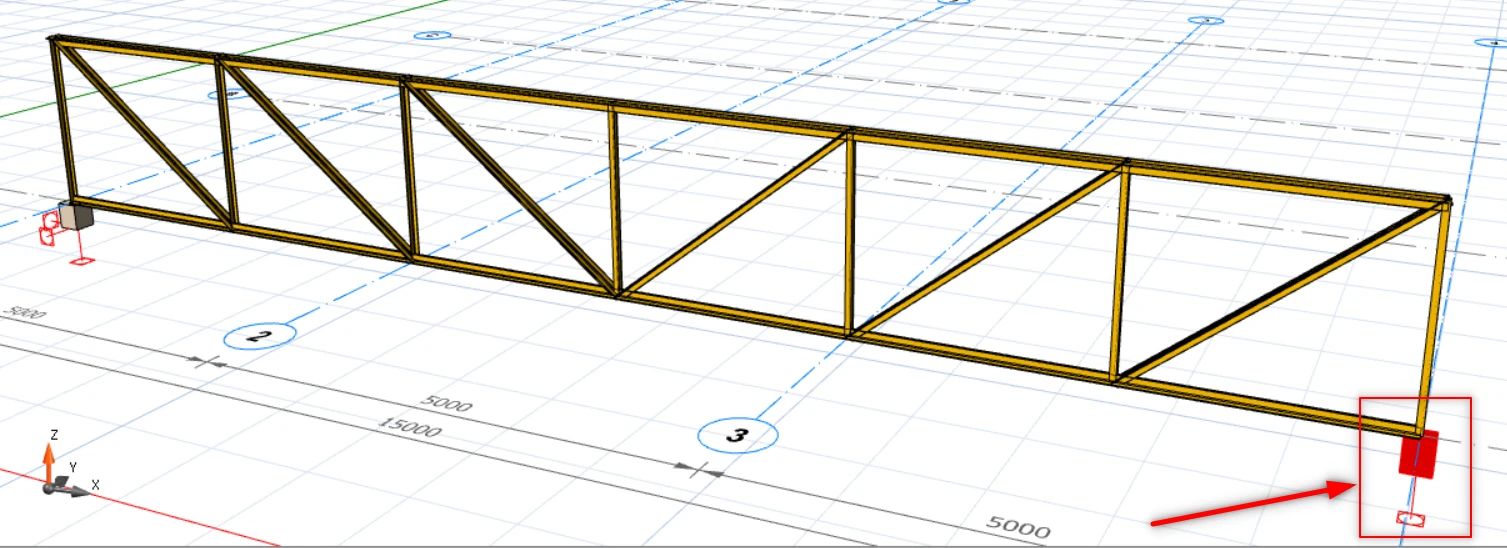
A simple example is shown below, where a truss is supported on a default fix support on the left end, and roller support at the right end.
Restraint Symbol at the Support
In the ProtaStructure, there are 2 types of restraint at the support : Translation Restraint and Rotation Restraint.
In the picture below is an example of the restraint visualization of a fixed support, with both rotation and translation restrained in the 3 degrees of freedom.
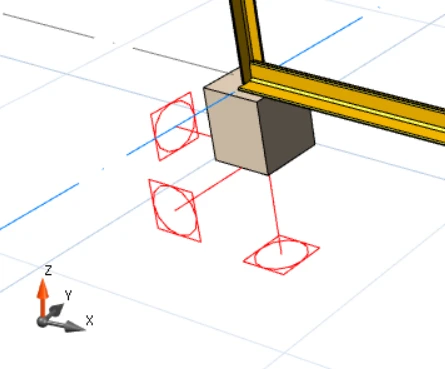
Square = Translation Restraints
Circle = Rotation Restraints
By default, whenever a column or wall is inserted in ST 01, it will automatically be assigned a fixed support as above.
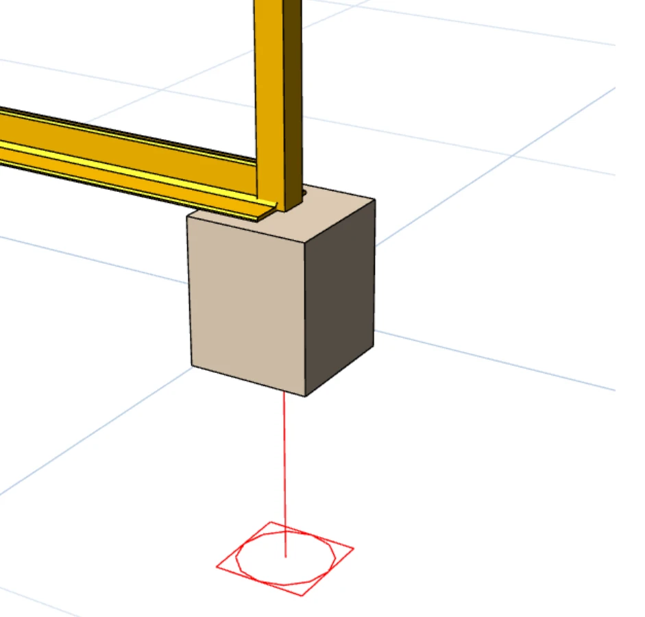
Thus for roller support, the only restraint acting upon it will only be at Z-direction as shown below.
The steps in creating a truss supported by different supports are as follows :
1. Insert Short Columns as the Truss Supports
Firstly, 2 short columns have to be inserted to provide support for the truss.
The purpose of a short column is to ensure the support is very stiff to minimize the 3D behavior of sway or deflection out of the plane.
There are 2 ways to insert a short column in ProtaStructure :
1. Change the column height by editing the Storey Height : Storey Related Controls and Settings – Edit Storey2. Edit the del-z value of the column : Working with Columns – del z (Top) & (Bot)
When a column is inserted at ST01, a fixed support is automatically created. Hence there is no need to change the support type of the column at the left end.
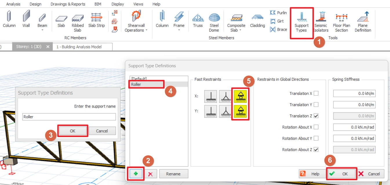
2. Create Roller Support & Assigning it to the right end Column
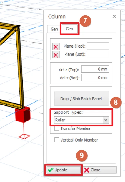
1. Go to Modelling Tab2. Click Support Types3. Add and name a new support type as 'Roller'.4. Choose Roller and set the restraints to roller support. Direction is up to user's choice.5. Click OK.6. Double-click on the right end column to bring up the Column Properties window.7. Go to the Geo Tab and change the column support types to "Roller".8. Click Update.
Refer to this article for more detailed explanation on the Support Types function : Support Types
3. Create the Truss
Go to the 3D view and create the truss by activating the "Truss" element in Modelling tab and then clicking on the top of the 2 columns.
4. Check the Structural Behavior via Analytical Model
You should verify the validity of the analysis by examining the analytical model forces and deflection via Analytical Model view.
Open the Analytical Model after running the Building Analysis, go to Results Tab and make sure to click the Displacement and Animation.
Here, the user can verify the structure's behavior. As shown below, the truss at right end is indeed behaving like a roller, because of the assigned roller support.
