Defining A New Brace
Defining a New Brace
In order to define new braces follow the below steps:
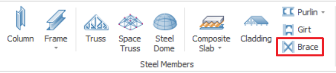
- Click on the "Brace" button from "Modelling" ribbon or you can use command line at right bottom corner.
- Pick two consecutive columns or beams.
- Brace dialog will be loaded.
- Press "OK" button to close the "Brace" dialog.
- In order to open Brace properties double left click on Brace members or left click and open Properties.
At properties dialog, you can change the brace properties that listed below:
Section and Type:
- At "Profile" section, you can set the section type.
- Brace types can be set as Diagonal, X Brace, V Brace, K Brace.
- In order to determine the out of plane movement of braces, set the "Out of Plane Alignment".
- Set the out of plane alignment by using "Custom Offset"
- In order to match the physical alignment of braces and center of column, define the "In Plane Alignment".
- Use the "Divide" option to divide one of the brace members. This option will help you to model the brace connection, in ProtaSteel.
- As default, brace ends are modeled as pinned. In order to have fixed ends, use "Model Joints as Fixed" option.
Top/Bottom Offsets:
- You can edit offsets from original insertion points. You can apply these changes into building model by using "Applt Top/Bottom To Analysis" option.
- Offset parameters are shown at left bottom corner.
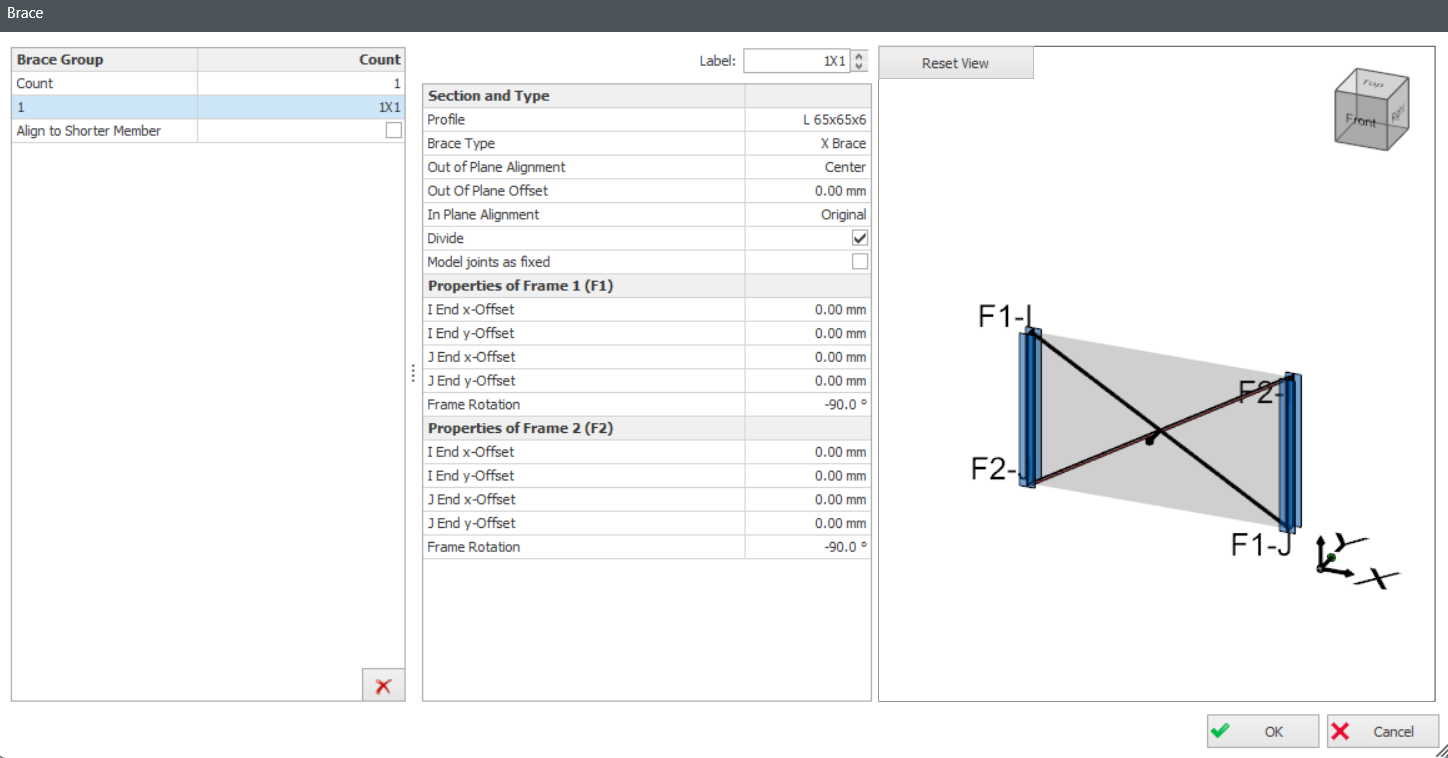
Brace Group:
- Insert Brace Group by editing "Count" and "Interval".
Count: Insert Brace Group by quantity. Press
CTRL for multi-selection, selected braces will be reflected as green.
Interval: Insert Brace group by interval.
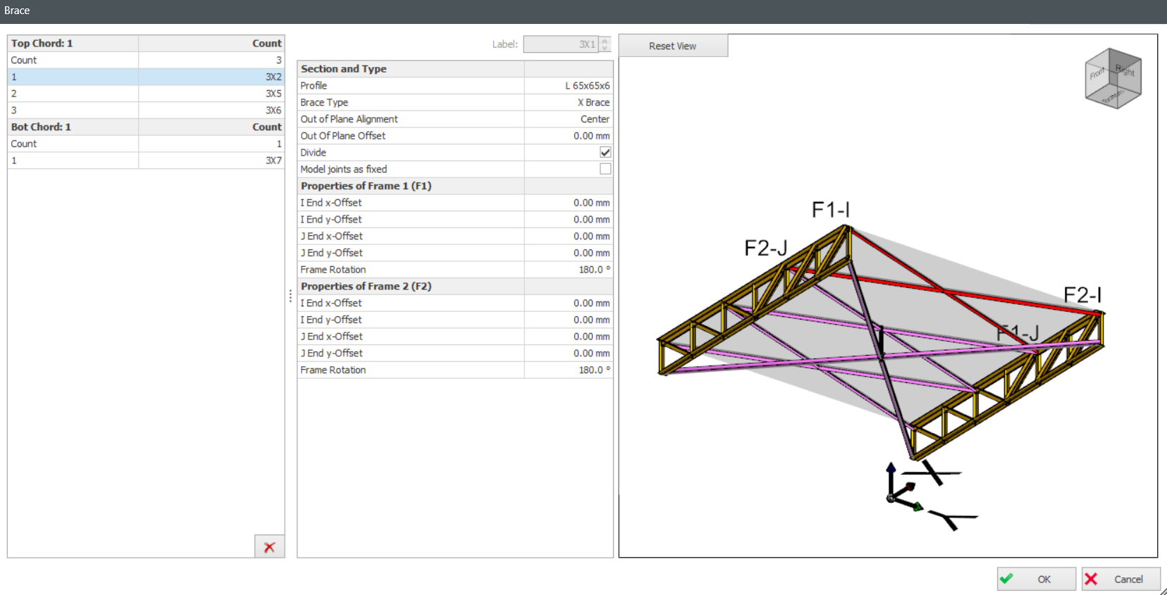
Defining Braces between Truss Members
- Click Brace button and select two trusses. Brace dialog will be loaded.
- Braces will be inserted as groups. In order to not insert brace group use "0" as count.
- Press CTRL for multi-selection, selected braces will be reflected as green.
- You can change properties of all selected braces together.