

Before proceeding with the modelling of the transfer beam, it is important to understand how the physical model translate to an analytical model when building analysis is performed.
- The physical model is what you see on the modelling screen where all members are rendered in 3D according to the actual sizes
- The analytical model is a wire-frame model that is created by solver which is actually what is analyzed finally.
- The analytical model can be viewed by clicking Analytical Model in Analysis tab.
Physical Model Versus Analytical Model
In ProtaStructure, we can visualize all members as single line wire-frame created along the axis or axes intersection:
- A column will be a single line wire frame at the intersection of 2 axes.
Physical Model Analytical Model
- A beam is a single wire-frame line along the insertion axis. Hence for the column and beam members to connect properly, they need to meet at the exact axes’ intersection.
Physical Model Analytical Model
Transfer Beam Supporting Discontinuous Column
When modelling a discontinuous column supported by a transfer beam, the column should use the same longitudinal axis as the beam to be supported. In the example below :
- The transfer beam is modeled using axis 1
- The upper column is inserted using intersection of axis 1 & C
- The lower column is inserted using intersection of axis 2 & D
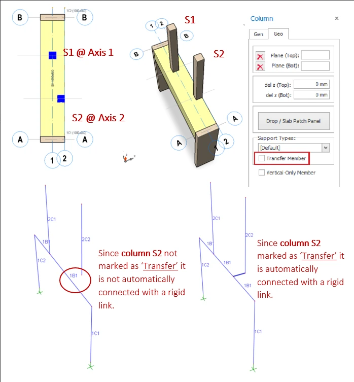
1. Mark the column as "Transfer Member" in Column Properties & rigid links will be automatically created during the analysis to join the bottom of the column to the transfer beam.2. Manually create a "dummy" beam to join the bottom of the column to the transfer beam (if auto-rigid link does not work)
Transfer Columns with auto Rigid Links
- The design of beams supporting these transfer members will be correct.
- Discontinuity message will not be issued for marked transfer members during the analysis.
- Additionally, if transfer columns are inserted on different gridline from that used by transfer beam, the analysis will automatically created during the analysis to join the bottom of the column to the transfer beam.
Support Offset Transfer Column with Dummy Beam
- Click Beam element icon
- Connect the dummy beam from the transfer beam axis to insertion axis of the discontinuous column
- The dummy beams may be of any size and will be considered as rigid links to connect the transfer beam and the eccentric discontinuous column.
After the analysis, recheck the Analytical Model, which shows the lower column is now supported by the transfer beam (via a rigid beam) :
Transfer Beam Supporting Discontinuous Wall
A wall is a single plane along the longitudinal insertion axis. Therefore, for a discontinuous wall to be supported by the beam, both the beam and wall members must share the same longitudinal axis.
1. "Transfer Member" must be checked (similar to transfer column)2. "FE Shell Model" must be selected for wall analysis type (instead of Mid-Pier)
Physical Model
- As shown in the Analytical Model above, the Mid-Pier assumption will be unrealistic or unreasonable as the transfer wall will exert a point load in the middle of the wall. This inaccuracy will worsen with longer transfer wall.
- The FE Shell model will give an accurate & realistic result as the transfer wall loading on beam approximate that of a uniform load; as each shell will exert a separate load on the transfer beam.
Supporting Offset Discontinuous Wall with Dummy Beams
- Create ghost axes for the dummy beams.
- Connect the dummy beam from the transfer beam axis to the axis of the transfer wall.
- Ensure that appropriate intersection points are available for the creation of the wall and beam elements.
- The dummy beams may be of any size and will be considered as rigid links to induce the appropriate forces onto the transfer beam.
As shown in the example model above, the dummy beams will be converted to rigid link during the analysis and will result in :
- The load transferred from the discontinuous walls to the transfer beam
- Induced torsional moment to the transfer beam
![]()