Axial Load Comparison Report Example

| Beam Size | : 250mm (width) x 500mm (depth) |
| Column Size | : 250mm x 250mm |
| Column Height | : 3000mm |
| Slab Thickness | : 150mm – therefore self-weight = 3.6 kN/m2 |
| Loading on slab | : Self-Weight (calculated automatically based on thickness of slab) |
| : SDL = 1 kN/m2 | |
| : Total Dead Load = 4.6 kN/m2 | |
| : Imposed Load = 0 kN/m2 |
The purposes and validity of the comparisons that can be made between the sections of this table are discussed in the following sections.
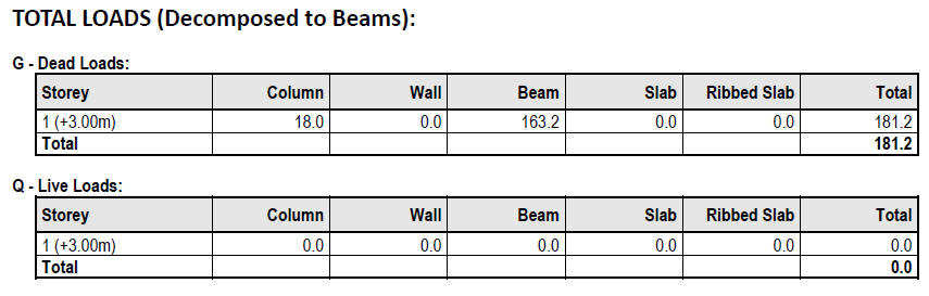
Table 1: Total Loads (Based on Slabs)
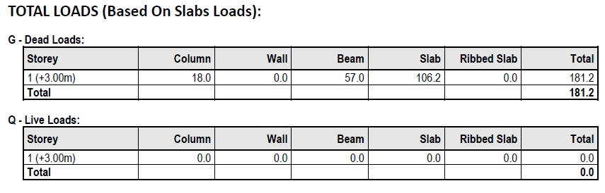
- Member self‐weights
- Applied loads on columns/walls
- Applied loads on beams
- Applied loads on slabs
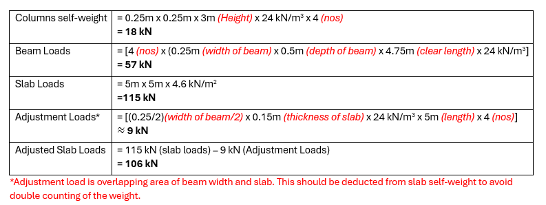
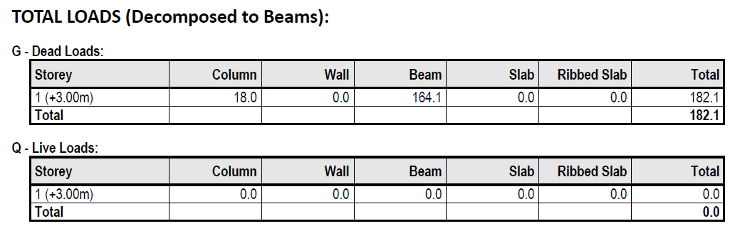
Table 2: Total Loads (Decomposition to Beams)
Using Yield Line Decomposition
- Member Self‐weights
- Applied loads on columns/walls
- Applied loads on beams
- Applied loads on slabs
The key difference in this table is that the slab loads are now decomposed and thus counted as UDL’s, VDL’s etc. on the supporting beams. Therefore, you will find that the slab loads become zero, but the beam loads increase accordingly.
Decomposed Slab Loads – Consider again the model and the decomposed slab loads shown below.
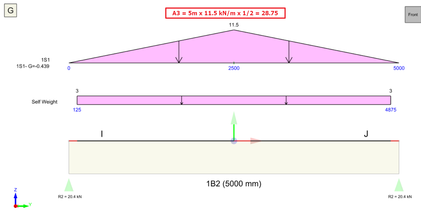
The plan view shows the yield lines, strictly speaking these are really just load decomposition lines which are used to show the area of slab loading that will be attributed to each beam. This method of area load decomposition is commonly known as the Yield Line Method. Looking at the triangular load distribution generated on the above beam, the beam load calculation effectively becomes:
Decomposed Slab Load = (A1 + A2 + A3 + A4) kN/m2 <Please refer to diagram> – adjustment loads
= 4 x 28.75 kN – 9 kN
= 106 kN
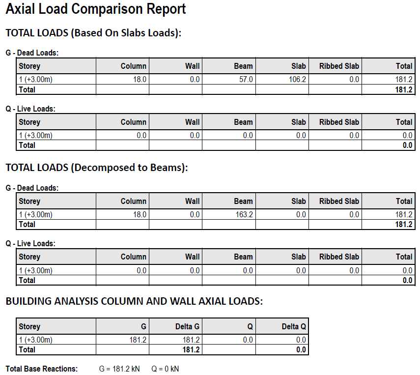
The calculations reported in Table 2 are therefore as follows:
Columns Self Weight = UNCHANGE
= 18 kN
Beams Loads
= 57 kN + 106 kN
= 163 kN
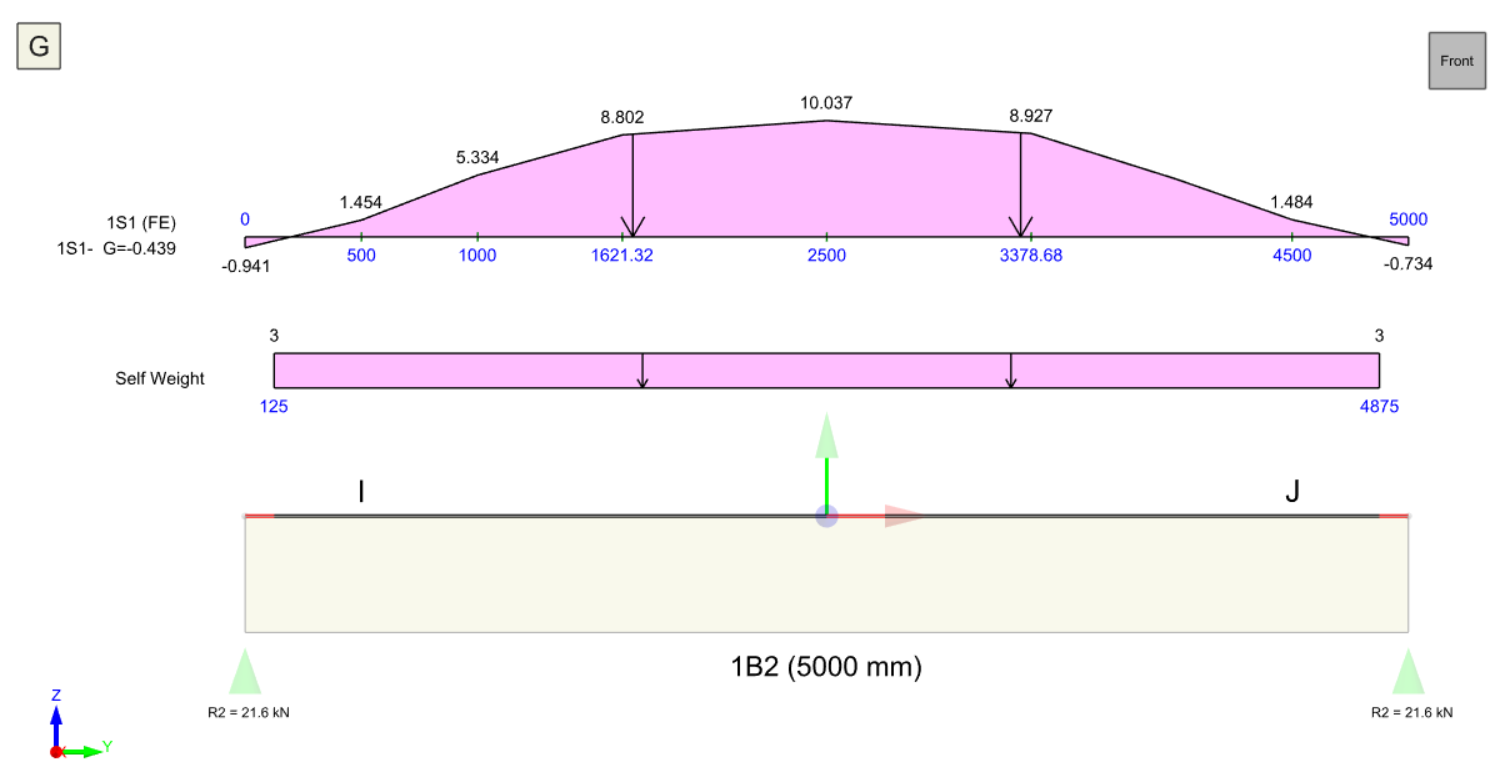
Using Finite Element Decomposition
Comparisons between Tables 1 and 2
- Check that slab loads are applied within slab boundaries
- Visually Check Yield Lines – if they do not look right on the plan the decomposition is probably not right.
- If Yield Lines are wrong, consider swapping to the FE Load Decomposition method.

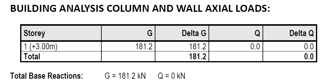
Table 3: Building Analysis Column and Wall Axial Loads
Axial Load Comparison Warnings
- If there were warnings during the building analysis, the warnings should not be ignored and corrective action should be taken.
- Check whether the discontinuous columns and beams are properly supported.
- Use "Load Decomposition by FE" instead of "Yield Line Method" to ensure loading on slab (ie. nodal load, UDL). For more detail, please refer to Yield Line and FE Load Decomposition with Example.
- Make sure "Similar Storey" set in "Edit Storey" should have the same storey height. For example, if 2nd storey with 4m height and 3th storey with 3m height set as similar storeys, this will causes axial load comparison error. Exclude the storey which has different height will solve this issue.
Axial Load Comparison Warning Limitation
- Too many (i.e. 4 or more) "Plane Definition" created at the same storey. This will affect the loading captured in table 1.
- "Plane Definition" created on top of a slanted slab (i.e. Ramp). This will affect the loading captured in table 1.
- “Support Type” is defined in beam. This will affect the loading captured in table 3.
- Loadings applied on sag rods.
- Dome applied on a similar storey floor. This will affect the dome loading captured in table 1 and 2. Reset the similar storey to resolve this warning.
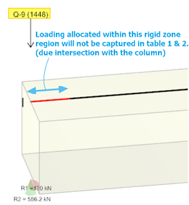
- Loading applied onto rigid zone (red). This loading will not be captured in table 1 and table 2 but correctly captured by table 3 (Building Analysis Result).