Base Plate Connection Macro Example Psteel 2022
Base Plate Connection Macro Without Design Example
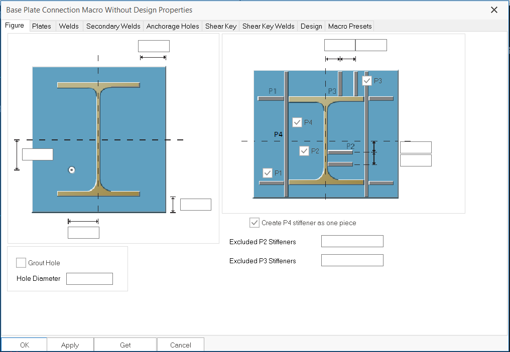
This connection macro creates base plate and places anchor bolt holes underneath a column. Placing the mouse cursor over the Base Plate Connection Macro Without Design will reveal the tooltip describing the scope and steps of this macro.
Right click the icon will call out the macro's properties, all parameters can be changed here:
The GIF below shows the steps to insert the macro:
- Click the macro icon
- Select the column
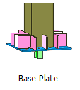
- The macro will be created.

This macro only applicable for I section steel columns.
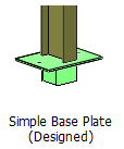
Simple Base Plate Connection Macro Example
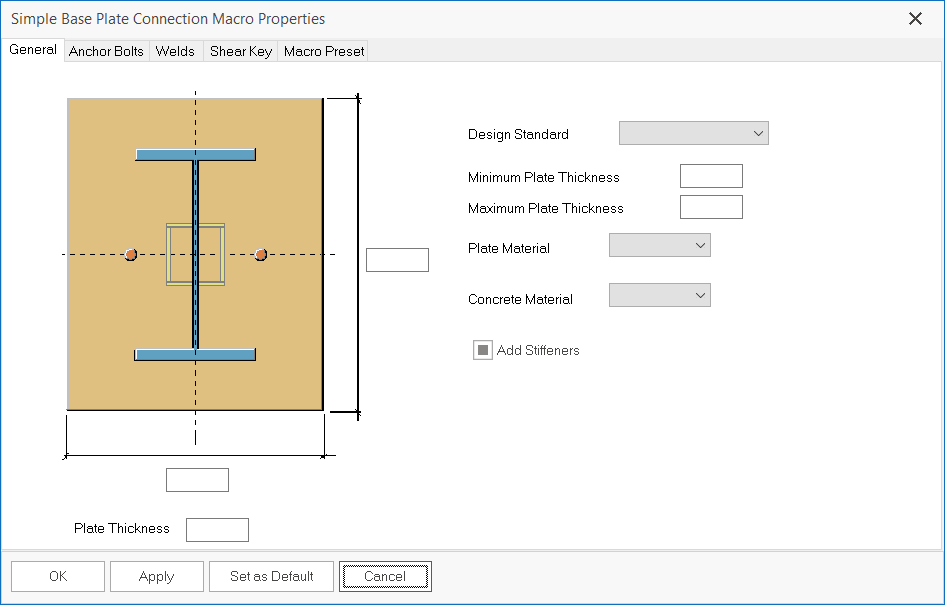
This connection macro creates a simple column base plate connection. Placing the mouse cursor over the Simple Base Plate Connection Macro will reveal the tooltip describing the scope and steps of this macro.
This macro can be designed and generated report. Right click the icon will call out the macro's properties, all parameters can be changed here:
The GIF below shows the steps to insert the macro:
- Click the macro icon
- Select the column
- The macro will be created.
This macro only applicable for I section steel columns.
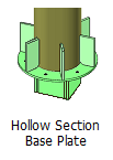
Hollow Section Base Plate Connection Macro Example
This connection macro creates a hollow section base plate. Placing the mouse cursor over the Hollow Section Base Plate Connection Macro will reveal the tooltip describing the scope and steps of this macro.
Right click the icon will call out the macro's properties, all parameters can be changed here:
The GIF below shows the steps to insert the macro:
- Click the macro icon
- Select the column
- The macro will be created.
This macro only applicable for hollow circular or hollow box steel columns.

- Create the most appropriate View first before creating the connection. The same view & orientation will be used to produce the drawings. Click this topic for more details: Creating Views
- Press F9 on the joint to set the point of interest. The view will then rotate about the point of interest