Drawing Module
1. Create the desired View in Model Explorer > Views
2. Ensure the orientation of the view you want to use in the drawing is correct as the drawing module will automatically use the latest views.
 Double-click on the View > Press F4 to reset the view to default
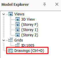
 4. Start the Drawing module by double-clicking Drawings in the Explorer pane (Ctrl + D)
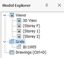
Modeling Views
In the Drawing Module, the same views that were created in the main model will be listed under the Explorer > Modelling Views :
- 3D View – 3D view of the model
- Storey F – foundation plan view (ST00 in ProtaStructure)
- Storey 1 – Storey 1 plan view as defined in ProtaStructure
- All other storey plan views as defined in ProtaStructure
Drawing Manager
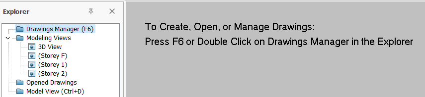
The Drawing Manager is where you can start a new drawing.
1. Double-click on Drawing Manager (or F6)
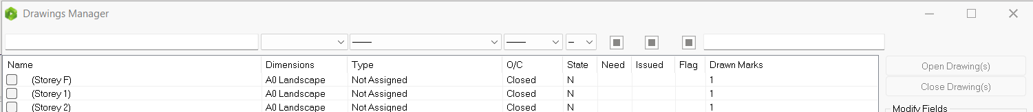
2. The Drawing Manager allows you to manage the drawings :
- Open Drawings
- Close Drawings
- Create Drawings
- Create Copy
- Delete Drawing(s)
- Rename
- Import
- Custom Paper Size
- DXF Exports
- DXF Settings
- Add Revision
3. To open a drawing, select the drawing name, e.g. (Storey 1) > Pick Open Drawing
Alternatively, simply double-click on drawing name to open it
4. Close the Drawing Manager & view the drawing
The outermost brown line represents the Drawing Border (e.g. A0 size).
The inner dotted blue line represents the Viewport Border
5. Double-click on any empty space within the drawing border to access the Drawing Properties
Drawing Properties
The outermost brown line of an opened drawing represents the Drawing Border (e.g. A0 size).
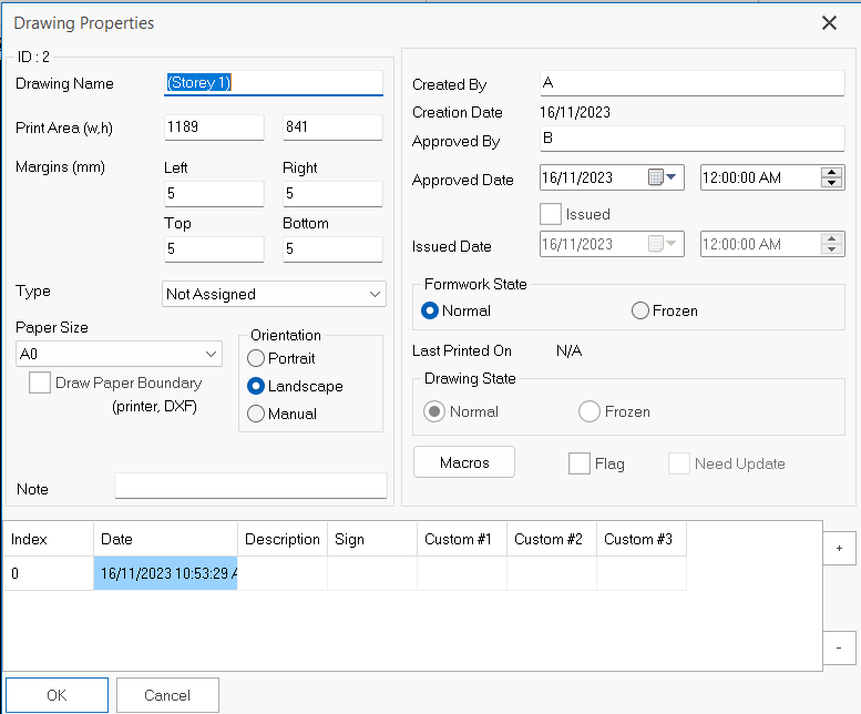
The Drawing Properties dialog has the following options / fields :
- Drawing Name
- Print Area (w,h)
- Margin (mm)
- Type
- Paper Size
- Orientation
- Created by
- Approved by
- Approved Date
- Issued Date
- Formwork State (Normal / Frozen)
- Drawing State (Normal / Frozen / Broken)
Viewport
A viewport must be created to indicate which part of the model & in what orientation to be shown in the drawing. The views created in the main model will become the view ports.
The steps to create a viewport are :
1. Create & open an empty drawing
2. Right-click on the specific Modelling Views > Create Viewport (as shown below)
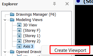
3. The viewport will be created with the part model shown within the blue border
4. To move the view port, place the mouse cursor over the blue border > left-click & drag to the desired location (as shown below)
5. To change the size of the viewport, place the mouse cursor at the lower-right corner > the cursor will change to resize > left-click & drag to resize the window
6. Double-click any place within the Viewport blue border to access the Viewport Properties
Make it as a practice to remember to close the drawing by clicking the "X" button at the top right corner or go to Drawing Manager (F6) to Close Drawing(s).
