Eurocode 8 Shearwall Moment Shear Design Envelope
To ensure that the ductile shearwalls, with H
w/Lw ≥ 2, remain elastic above the base hinge considering the uncertainties in the structure dynamic behavior, the design bending moments and shear forces obtained from analysis are magnified.ProtaStructure will now automatically calculate the tension shift and apply bending moment and shear force envelopes according to the procedure outlined in Eurocode 8 – 5.4.2.4.
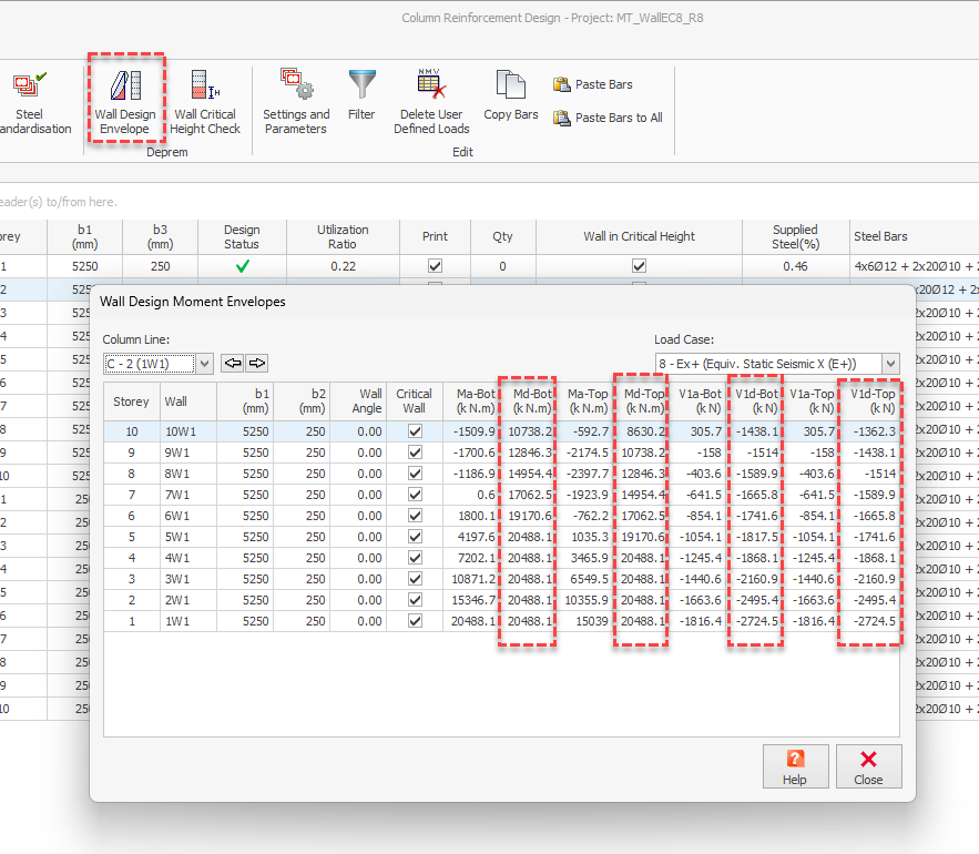
You can review and change the design envelope values from Column Reinforcement Design > Wall Design Envelope window.
Bending Moment Design Envelope
From the bending moment diagram obtained from the analysis, a linear envelope can be established.
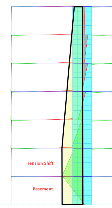
This diagram must be shifted upwards by a distance a
1, designated tension shift in Eurocode 8 – 5.4.2.4 (5), consistent with the strut inclination adopted in the Ultimate Limit State verification for shear.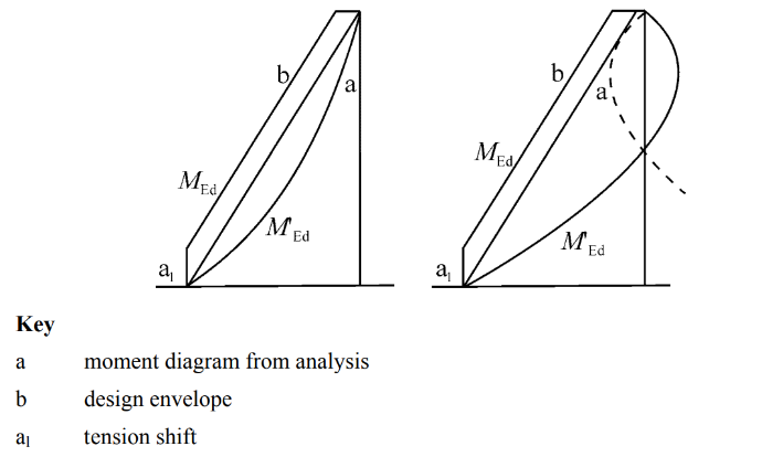
User-defined Strut Inclination Angle, θ, for Tension Shift Length
The default Strut Inclination Angle, θ, for tension shift calculation in ProtaStructure is 21.8°, which yields cot(θ) = 2.5.
The tension shift length is calculated with the formula a
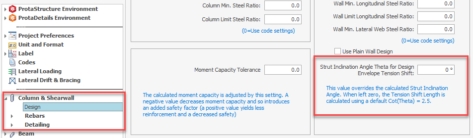
1 = Lw cot(θ).The value of strut inclination angle varies from 21.8 to 45 degrees. To leave room for individual interpretation, we have introduced a new setting, “Strut Inclination Angle for Design Envelope Tension Shift”. It is accessible from Settings > Column & Shearwall > Design.
The value entered here will override the calculated strut inclination angle. When left zero, the tension shift length is calculated using the default cot(θ) = 2.5.
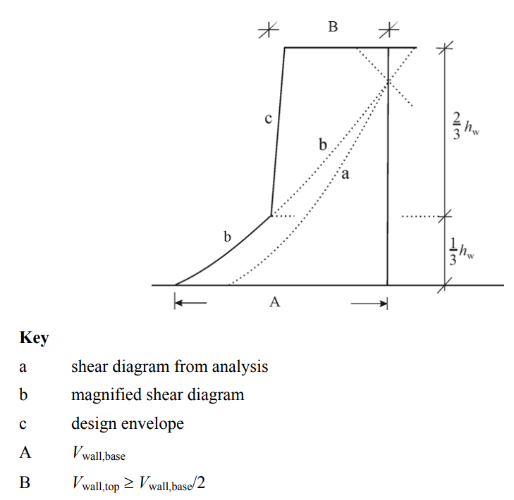
Shear Design Envelope
According to Eurocode 8 – 5.4.2.4 (6), the possible increase in shear forces after yielding at the base of a primary seismic wall, must be considered. This requirement may be satisfied if the design shear forces are increased by 50% (for DCM) than the analysis shear forces in the critical wall height extending Hw/3 from the building base or basement level. For DCH structures, the shear amplification factor is calculated by Eurocode 8 Eqn. 5.25.
User-Defined Shear Amplification factor, ε
ProtaStructure provides a user-defined parameter for shear amplification factor which can be edited for each wall line. The default and the minimum value is 1.5 and the maximum value is the ‘q’ factor used in the analysis in the wall direction. ProtaStructure will magnify the analysis shear forces are by this factor inside the critical height. The shear diagram is linearly connected to the value at the top, which is Vwall,base/2.

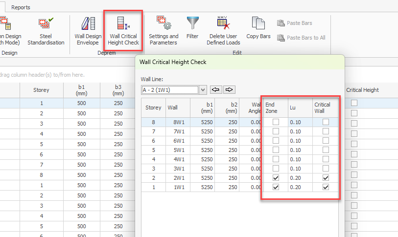
Shearwall End Zone (Boundary Elements) Batch Editing
Shearwall end zones or boundary elements are essential in ensuring a ductile behavior especially in critical plastic regions of shearwalls.
Each seismic code has different regulations in calculation and curtailment of end zones.
ACI and Eurocode follow a strain-based approach in end-zone length calculation while Turkish code requires a minimum ratio of the wall length.
Also, for some codes, end zones may not be necessary outside the critical height, while a reduced end zone length is used in the other codes.
ProtaStructure has been supporting shearwall and corewall endzones (boundary elements) for a long time now. In the new version it just improved. We now allow you to set the critical height, end zone usage and end zone length easily in a batch mode editor.
For core walls, user is expected to decide on the end zone layout using the automated tools in Polyline Wall Editor.