Lateral Analysis 29 4 2019
In the
Pile Design
calculation (ProtaDetails > Design Library), Lateral Analysis will analysis and design for pile combined axial and lateral shear or bending action.
Pile Design
calculation (ProtaDetails > Design Library), Lateral Analysis will analysis and design for pile combined axial and lateral shear or bending action.
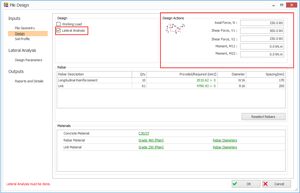
- Check the Lateral Analysis in the Pile Design > Design tab. The Lateral Analysis tabs will be visible on the left panel. Design Actions group box will be visible on the top right-corner.
Design Parameters
tab in the Lateral Analysis tab allows you to enter the following parameters:
tab in the Lateral Analysis tab allows you to enter the following parameters:
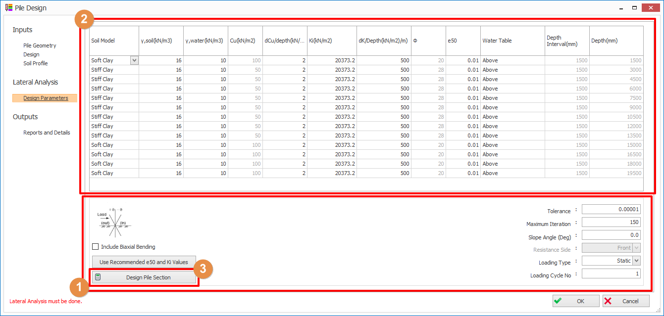
1. Design Parameters
- Tolerance: Allowable error of analysed results
- Maximum iteration: Analysis will stop at maximum iteration even though the error is greater than the tolerance.
- Slope Angle: If the ground is sloping or the pile is raking, please enter the relative angle in degree.
- Pile rotates anticlockwise with respect to ground surface, the slope angle shall be in positive sign
- Pile rotates clockwise with respect to ground surface, the slope angle shall be in negative sign
- Slope (Ground surface) rotates clockwise with respect to pile, the slope angle shall be in positive sign
- Sloe (Ground surface) rotates anticlockwise with respect to pile, the slope angle shall be in negative sign
- Resistance Side (only applicable if slope angle is not zero): if the soil is in passive on right-hand side of the pile, set this to Front. if the soil is in passive on left-hand side of pile, set this to Back.
- Loading Type: If this set to static, it indicates that the applied loading is static. If this is set to cyclic, the loading will be applied for number of cycles as defined in Loading Cycle No.
- Loading Cycle No. (only applicable if Loading Type is set to Cyclic): Number of cycles for the cyclic loading.
2. Soil Model
- Soil Model: You can choose various soil models for different type of soil namely, (i) Soft Clay; (ii) Stiff Clay; (iii) Sand; (iv) Void; (v) Linear Elastic (E constant) or (vi) Linear Elastic ("E" Incremental)
: Effective soil unit weight
: Water unit weight
- Cu : Soil undrained shear strength (can be edited in Soil Materials in Soil Profile tab)
- dCu/Depth: Increment of Undraind Shear Strength against depth
- Ki: Initial soil Stiffness
- dK/Dept: Increment of soil stiffness against depth
-
: Soil Friction angle (can be edited in Soil Materials in Soil Profile tab)
- e50: Strain corresponding to one-half the maximum principal stress difference
- Water Table: Above – water table above this soil layer; Below – Water table below this soil layer
- Depth Interval: Soil layer thickness (can be edited in Soil Materials in Soil Profile tab)
- Depth (Auto calculated): Bottom depth of this soil layer
3.
Click
Design Pile Section
in
Design Parameters
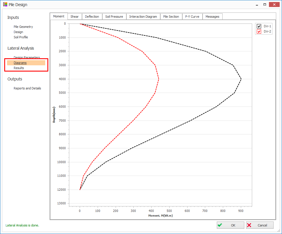
tab to perform the lateral pile analysis. Then, the
Diagrams
and
Results
tabs will be visible. The design bending moment, shear, deflection and soil pressure diagrams can be reviewed in the Diagrams tab for both direction 1 and 2.
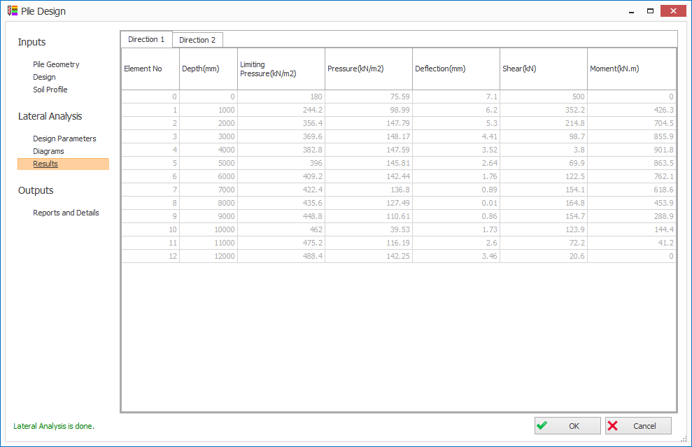
The tabulated analysis result can be reviewed in
Result
tab for both directions 1 and 2.
Result
tab for both directions 1 and 2.
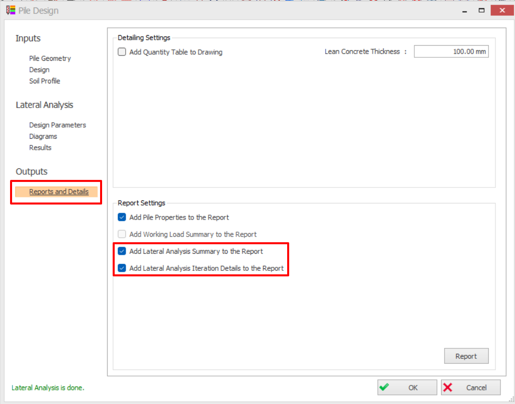
Go to
Report and Details
tab > Check
Lateral Analysis
> Click
Report
button to generate the report.
Report and Details
tab > Check
Lateral Analysis
> Click
Report
button to generate the report.

For theory and references of this calculation refer to :
Pile Design : Lateral Analysis Theory and Calculation Method
Pile Design : Lateral Analysis Theory and Calculation Method