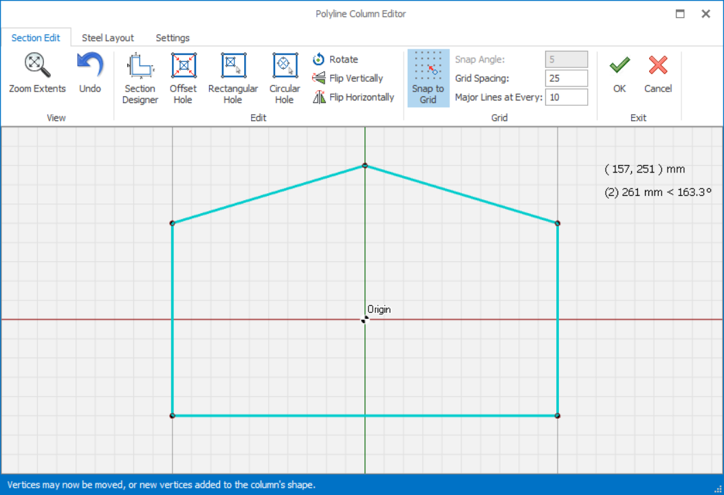
Polyline Column Editor
- Select the Column
- Click "Polyline Column Editor" icon in the top Column Ribbon
- Alternatively, right-click to expose the context menu > Choose "Polyline Column Editor"
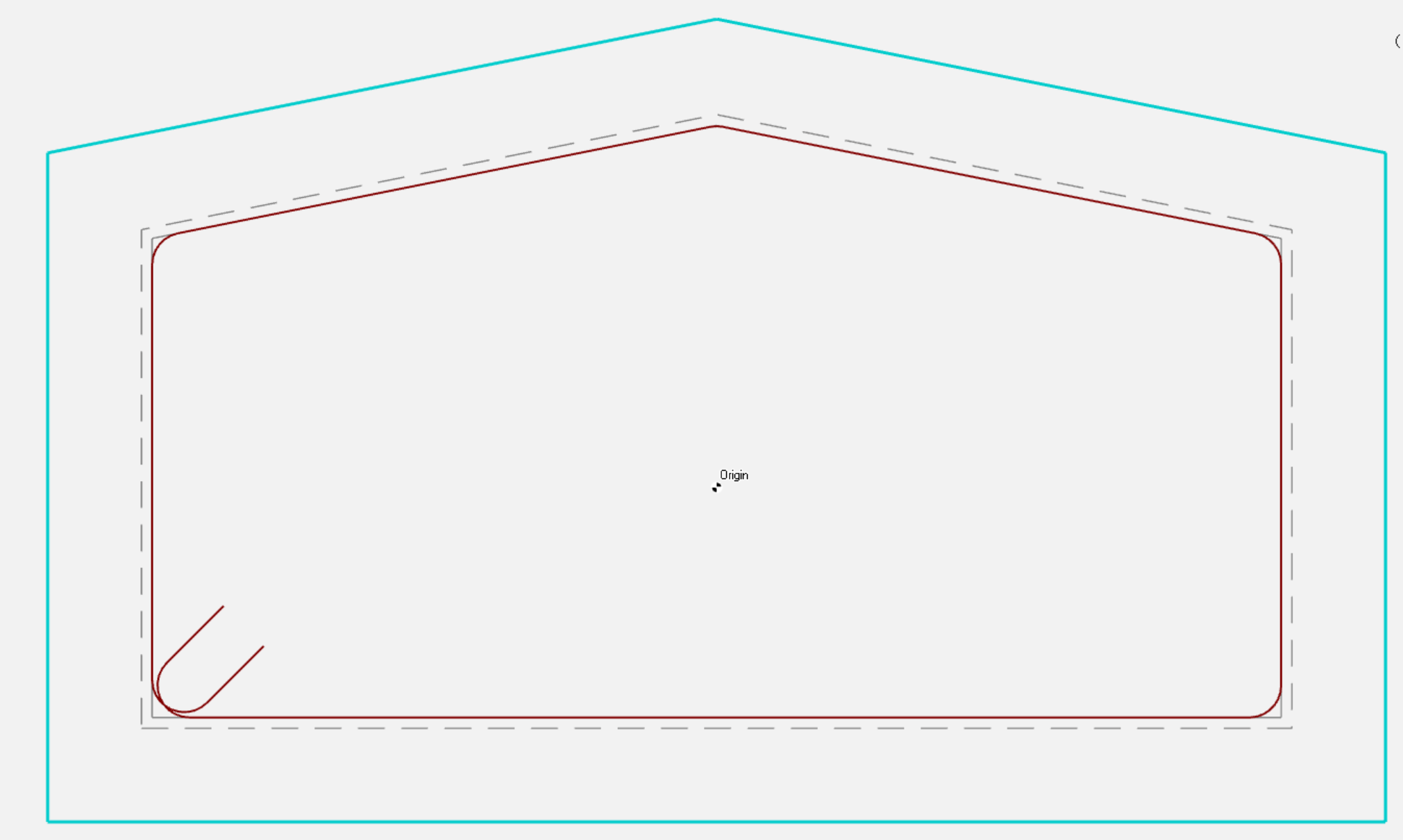
Section Edit tab
View Menu
“Zoom Extents” zooms to display the drawing extents. Moreover, “Zoom in”, "Zoom Out" and “Pan” operations can be performed by using the mouse wheel.
Click "Undo" as many times as you wish, backing up one step at a time, until the drawing is as it was when you began the current editing session. Alternatively, “Undo” option in the shortcut menu that is displayed by right-clicking can be used. When the shortcut menu is loaded, “Cancel” option can be selected in order not to do any operation.
Steel Edit Menu
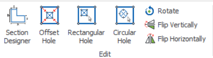
“Edit” menu includes "Section Designer", "Offset Hole", "Rectangular Hole", "Circular Hole", “Rotate”, “Flip Vertically”, or “Flip Horizontally” options.
Section Designer
- Common sections can be easily created by using the parametric options provided in this editor.
- When you select one of these column section buttons, related dimension parameters.
- Enter the parameters and choose “OK” button to create the shape in the drawing area.
- The new column will overwrite any existing column information.
Rotate, Flip Vertically & Horizontally
- Click the “Rotate” option
- Enter the rotation angle in the “Angle” field in the dialog.
- Click OK > The column will be rotated by the angle indicated, counter-clockwise.
You can flip section vertically or horizontally by using "Flip Vertically" or "Flip Horizontally" options respectively. The column section will be flipped 180 degrees based on chosen option.
Grid Menu
“Snap To Grid” option on the toolbar is enabled then the added vertex will be located on the nearest grid point.
Grid Spacing to be used in the drawing area can be controlled by the "Grid Settings" field.
Adding a New Vertex
A new vertex can be added by left-clicking anywhere along the column edge. The vertex will have the coordinates of the mouse pointer, but if the “Snap To Grid” option on the toolbar is enabled then the vertex will be located on the nearest grid point.
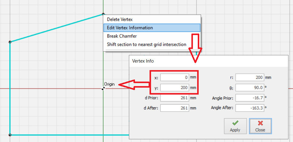
Editing Vertex Information
To move the any vertex, simply left-click & drag to any grid intersection.
Vertices of polyline section and holes can be chamfered either by using straight lines or segmented arcs.
- Right click on any of the vertices and select “ Break Chamfer” option.
- Enter the chamfer length in “Chamfer length” field in “Break Chamber” window.
- Maximum chamfer distance will be the minimum of two neighboring edge lengths.
- Right click on any of the vertices and select “ Break Chamfer” option.
- Select “Fillet” option to fillet the corner.
- Enter the arc radius in the “Arc Diameter” field.
- Precision of the arc can be adjusted by increasing the segment number in “Segment Count” field.
Removing a Fillet
Inserting a Hole Inside The Column
A hole can be inserted in a column by :
- Right-click on the drawing canvas > choose “Insert Rectangular Hole” or “Insert Circular Hole” options.
- Alternatively, click "Rectangular Hole" or "Circular Hole" in toolbar under "Edit" tab.
- Left click & drag inside the polyline section to draw the hole manually.
An offset hole can be inserted by clicking the “Offset Hole” icon located on toolbar. The offset distance will be asked for and the whole section will be offset inwards by the specified amount in order to form the hole.
Editing or Moving a Hole
Vertices of a hole can be edited by right-clicking on the vertex and selecting the “Edit Vertex Information” option. Furthermore, a hole can be moved by right-clicking on one of the vertices of the hole and selecting “Move Hole By Mouse” or “Move Hole By Entry”.
A hole can be deleted by selecting the “Delete Hole” option.
Steel Layout Tab
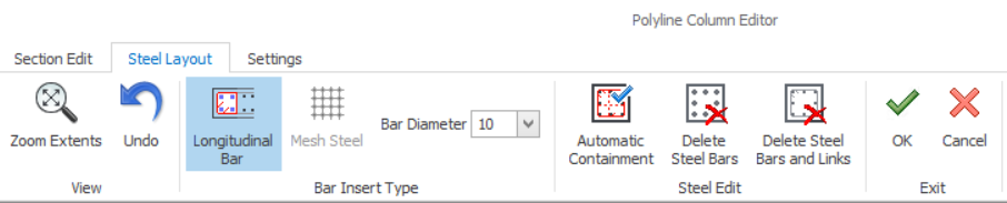

Automatic Containment
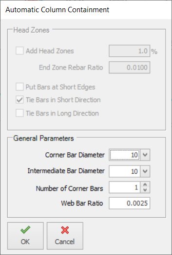
Head Zones
- Only applicable for RC wall where Head Zones can be inserted.
- These inputs are deactivated for column.
General Parameter
- Corner Bar Diameter : Select rebar diameter at the corner edge
- Intermediate Bar Diameter : Select rebar diameter between the corner edge
- Number of Corner Bars : Select number for bundle bars at corner edge
- Web Bar Ratio : Specify minimum area of steel, i.e area of steel divided by cross section area

Delete Steel Bars
Delete Steel Bars and Links
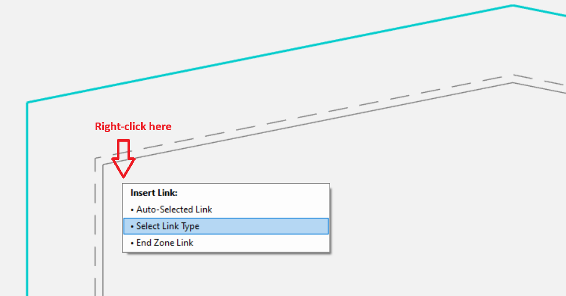
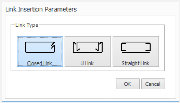
Inserting Links
Longitudinal Bars
- Select the Bar Diameter (click dropdown list)
- Click Longitudinal Bars icon
- Place mouse cursor at the corner grey grid > A grey square will be shown
- Click and drag in internal direction (black circle will be shown)
- Rebar will be added
 Insert corner rebar
- Place mouse cursor at the corner grey grid > A square will be shown
- Click and drag to the next corner (black circle will be shown)
- When the mouse cursor is at 2nd corner, a grey square is shown
- Release the mouse button > "Steel Bar Insertion" dialog will be shown
- Enter number of intermediate Bars & Select rebar diameter > Click OK
- Intermediate bars of equivalent distance will be inserted.
 Insert Bars
- Place mouse cursor on 1st rebar
- Left click and drag to the 2nd bar (mouse cursor will show a link)
- Release mouse click > Link is inserted
- Right Click on 1st rebar > Pick "Start Link Insertion"
- Click on subsequent rebars in anti-clock wise manner
- Finally click on the 1st rebar > Right Click
- A closed link will be inserted
 Insert Links
Exit Menu
This menu includes “OK” and “Cancel” options. The changes made will be valid if you close this menu using the "OK" button. If you press the "Cancel" button the changes will be discarded.
Settings Tab
The "concrete cover", "corner bar count", and "corner bar spacing" can be adjusted in the “Rebars” menu.
The colour of the background can be changed under the "Colour" menu.
You can select the link view style either "Section View" or "Line View" in "Link" Menu.