Protastructure Design Guide Loading Generator
Scope
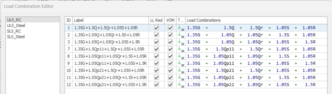
ProtaStructure can automatically generate the load
combinations as required by different design codes. To generate load
combinations automatically use the Loading Generator under Analysis
> Building Analysis > Load Combinations. This document explains the different
options in the loading generator.
Dead and Live Load Cases
Dead and live load cases must exist in all projects. That’s
why it is not allowed to uncheck these two in ProtaStructure.
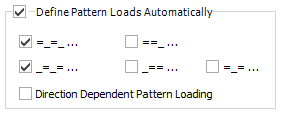
Pattern live loads are optional. By default, only odd and even
loaded span pattern is used. You can optionally check the other three patterns
and include in the combinations.
Separate pattern load cases are generated for each
orthogonal direction if “Direction Dependent Pattern Loading” is
checked.
Roof Live Load Cases
Generally in codes, it is recommended to define different
load cases for Roof Live Loads and it is
recommended to included in the loading
combinations with different coefficients. Especially these definitions are
important in steel structures where roof loading is prominent.
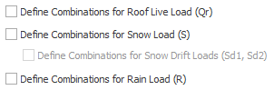
By checking these options, instead of using "Live Load State (Q)" for roof level slabs and elements (such as roof cladding, purlin, beam.), you can define individual load cases for :
Lr in ASCE-based specifications)
If you define a load
in the "Live Load (Q)" field together with "Roof Live
Load (Qr)" for a member at
roof level, both of these loads will be applied together. Therefore, a load
should not be defined in the "Q" field for such elements, unless
specifically preferred.
Construction Stages Load Cases
Dead and live load
cases can be defined as a part of construction stage. Optionally, you can have
a second independent set prepared for construction stage combinations that will
enable you to envelope the results with unstaged cases.
Seismic Loading
Four load cases (Ex +, Ex-, Ey +, Ey-) including positive and negative eccentricities are defined for earthquake loads calculated
in accordance with the selected earthquake codes. The "+" and
"-" signs in the load case labels indicate the side of the eccentricity
with respect to floor mass center. (i.e. rotating the floor CW or CCW)
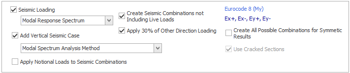
favorably. You can optionally include this in loading generator.
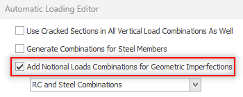
Notional Load


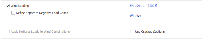
Wind Loading
Generally, two load cases are sufficient for the wind loads for
standard buildings where windward and leeward facades are similar. Load combinations
are automatically created separately for the positive and negative directions.
However, it is necessary to use different load cases in
positive and negative directions to define the wind load, especially for the buildings
with different windward and leeward facade areas, the cladding and purlins on
the sloping roofs of steel structures, and the girts on their surfaces. For
this purpose, you can define 4 load cases by using the "Define Separate Negative Load Cases" option.
In the ASCE-based wind loading definition, 4 load cases
(Wx, Wmx, Wy, Wmy) are generated by default since the torsion moment is
calculated for each direction. If you use the "Define Separate Negative Load Cases" option, you can use 8 load cases by creating separate
load cases for the negative directions.
Minimum Horizontal Loading
Especially in non-seismic regions, design codes provision
the application of a minimum horizontal load (notional loads) to buildings. By
definition, this includes the minimum lateral
loads that can be caused by constructional defects in the structure and
is usually calculated as a percentage of the building weight.
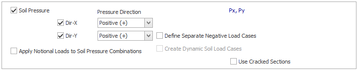
Soil Pressure
You can check the “Soil Pressure” load cases to describe the
soil pressure effects. (For example, span loads applied to the basement shearwalls,
or storey loads defined by storey loads editor)
In case the soil pressure is unilateral, it is sufficient to
define one or two load cases. By checking the option for relevant direction,
you can create soil pressure load cases and associated combinations.
Design codes suggest different combination coefficients for the
soil load cases for situations where the soil pressure is applied favorably or
unfavorably with other horizontal loads.
In this case, you must specify the direction in which the load is applied. For
example, if "negative" is selected for the direction of 1, the soil
load coefficient will be "0.9" in the earthquake loading in the
positive direction, and "1.6" in the earthquake loading in the same
negative direction.
However, if you want to define different positive and
negative load cases in both directions, you can check the "Define Separate Negative Load Cases" option to create 4 load states (P+x, P-x, P+y, P-y).