Rigid Links Auto Created To Support Offset Beams Supported By Columns
Introduction
During modelling
structures, there may be situation where the beams insertion point is offset from columns
insertion point. In other words, the beam end node may not coincide exactly with the column node.
falls within the boundary of the column, rigid links will be auto generated to ensure the beam is supported by the
column.
Simple test model
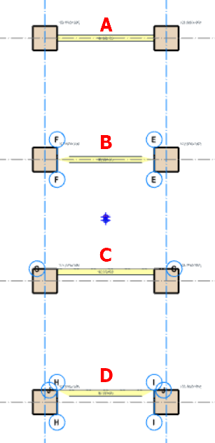
Four simply supported
beams are created with different end nodes insertion point:
- Beam A – Both beam end
nodes intersect with column nodes - Beam B – Both beam end
nodes are at the column edge - Beam C – Beam gridline
offsets from column gridline - Beam D – Beam gridline
offsets from column gridline and beam nodes are at the column edge
Parameters:
| Beam span : | 5m |
| Beam self-weight : | 3kN/m |
| Dead Load : | 10kN/m |
| Live Load : | 30kN/m |
Analytical Model & Results
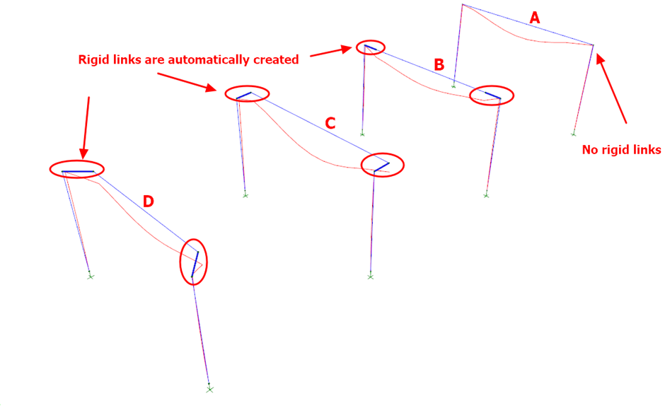
Figure 2
With reference to the above analytical view :
- The blue line is the analytical wireframe of the beams and columns.
- The dark blue line is a rigid link which is automatically generated in the analysis to ensure the offset beam is supported by the column.
- The red line is the deflected shape.
- For model A, no rigid link is created as the insertion node of column & beam is the same.
- For model B, the rigid link is created to face of the column since the beam insertion node is at the face of the column.
- For model C, the rigid link is created out of the plane of the frame to the edge of the column.
- For model D, a diagonal rigid link is created from the centroid of the column to the corner edge of the column.

Frame Load
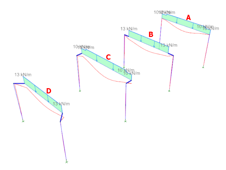
- Beam A & C :
- The user-defined UDL of 10 kN/m is applied to the center-line / insertion point of the column.
- The self-weight of the beam of 3 kN/m is taken to the edge of the column, which is more accurate.
- This explains the change or "kink" in frame value at the face of the column, from 10 kN/m to 13 kN/m.
- Beam B & D :
- Both the user-defined UDL & self-weight of beam is taken to the insertion nodes of the beam ends.
- Hence there is no "kink" in the frame load along the entire span of beam.
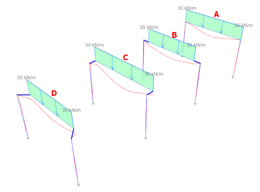
- As expected, there is no change or "kink" in the Q load frame values. A single value of 30kN/m is applied between the end nodes of the beam.
- The only difference is the length on which the uniform load is applied, due to the different insertion point used.
Axial Load
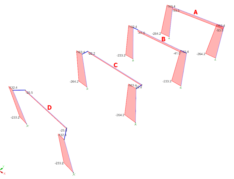
Figure 5
- The column supporting beam A has equal axial loads as column supporting beam C.
- The column supporting beam B & D has the same axial load & is lower than that of A & C.
- This can be explained by referring to the frame loads as shown in figure 3 & 4 :
- Column supporting beam A & C has higher axial load as the frame loads are taken from center-line of the column; hence the load length & total load is higher.
- Column supporting beam B & D has lower axial loads because the frame loads are taken to the face of column; hence the load length & total load is smaller.
Moment M33
The major moment M33 diagram, i.e. in the plane of the frame, due to ultimate load combination 1.4G + 1.6Q is turned on a shown below.
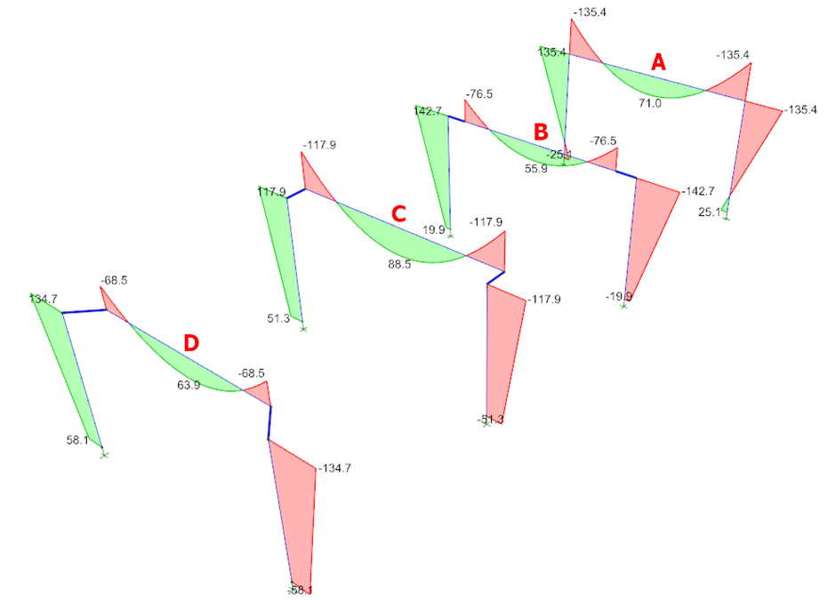
Figure 6
There are differences in the moment diagrams :
- Model A :
- The bending moment diagram is taken to the centerline of the column which coincides with the beam nodes.
- This is the simplest center-line wire frame model which will serve as base of comparison.
- Model B :
- The moment values for beam is lower, compared to Model A, because the frame loading length is the face of the column, i.e. shorter – hence the total load on beam is lower.
- The moment of the column is higher due to additional eccentric moment generated by rigid link. The eccentric moment generated is equivalent to the shear force at the beam end multiplied by the rigid link length.
- Note the beam end moment value is not the same as top column moment due the rigid link.
- Model C :
- The bending moment profile is similar to model A.
- However, the values are smaller due to the existence of the rigid links – the analytical model is thus different & not comparable considering additional 3D effect
- The 3D effect can be seen in figure 4 : Model C is also deflection out of the plane of frame.
- Model D :
- General behavior is similar to Model C, except a diagonal rigid link is created to the corner edge of the column.
- However, the maximum hogging moment of beam is considerably smaller than Model C, due to the shorter beam length & hence lower total load.
- The maximum moment in the column is higher due the the longer rigid link, resulting in higher eccentric moment induced by the offset beam.
Moment M22
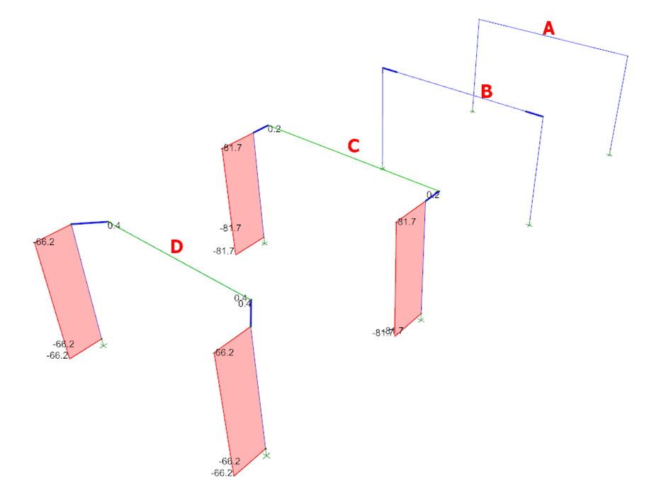
Figure 5
With reference to the diagram above :
- Beam A & B : No minor moment induced as the analytical model is fully in a single vertical plane.
- Beam C & D : There are moment induced in the column with offset beams (Beam C and Beam D) in
minor direction (out of the plane of the frame).

Conclusion
From the above investigation & result, we can summarize & conclude the following :
- Model A has no rigid link generated, the same maximum hogging moment in the beam is transferred to the column.
- Model B introduced complexity of rigid link unnecessarily – resulting in lower hogging moment at beam ends.
- It is easy to verify model A result with hand calculation & any other analysis program.
- Model B result cannot be verified using hand calculation due to rigid links. Results can only be verified with other 3D analysis program that is capable of generating rigid links.
- Model C max hogging moment at beam end tallies with moment at the column end.
- Model D beam max hogging moment at beam end is much lower than model C, the design will be unconservative.
- Overall Model C results proves to be more reasonable & in-line with traditional assumptions.

Rigid links
are not auto-generated for shear walls. Beam insertion must coincide exactly
with the wall insertion axis.