Seismic Analysis To Philippines Nscp2015
ProtaStructure can calculate seismic loads in accordance with Philippines (NSCP2015) seismic code, which is an adaptation of UBC97.
Go to Building Analysis dialog > Pre-analysis tab :
- Click on Settings Center > Code section will be shown > Pick Earthquake Code
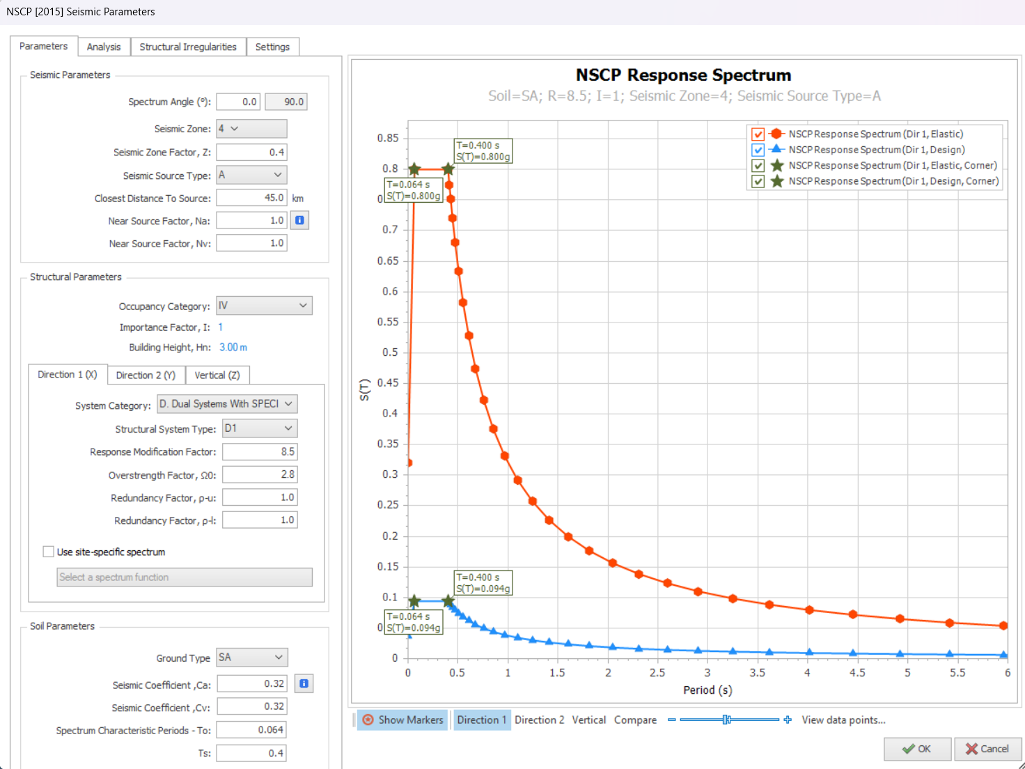
- Click Seismic Parameter to access the Seismic Parameters & settings
Click the i icon for more information and guidance on the parameter.
Parameters
The following are explanation of key inputs in “Parameters” tab :
- Spectrum Angle : Is the angle of the applied seismic forces with respect to the orientation of the structure on plan view; measured anti-clockwise from global horizontal. For example, if a rectangular building is modelled at a rotated angle, then the spectrum angle should be changed accordingly.
- Seismic Zone & Seismic Source Type : User to select
- Closest Distance to Source : Enter value & press “Enter”
- Near Source Factors, Na & Nv : Are automatically updated according to “Closest Distance to Source”. Click on ‘i’ for detail information & reference.
- Occupancy Category : User to select.
- Importance Factor is automatically fetched from the code.
- System Category & Structural System Type : User to select for each Direction 1(X) & 2(Y).
- Behaviour Factor (R) and Overstrength Factor (Ω0) are automatically fetched from tables in the seismic code.
- Ground Type (Soil Parameters) : User to select and all other fields Ca, Cv, To & Ta will be updated.
If a selected Structural System Type is not permitted for a given Seismic Zone and Building Height, an appropriate warning message will be shown.
Analysis
The following are explanation of key inputs in “Analysis” tab :
- Apply Accidental Eccentricity (5%) : Check to apply
- Damping Ratio : User input according to building type. Generally, 0.05 (5%) for concrete structure and 0.02 (2%) for steel structure.
- Number of Horizontal Modes : User input (recommended value = 15)
- Number of Vertical Modes : User input (recommended value = 15)
- Use user-defined periods in equivalent static analysis : Check to apply & input Period in X & Y direction
ProtaStructure will check the number of modes automatically & issue a warning during analysis if cumulative mass participation is not satisfied.
- Structural Usage or Type : Static field that appears on the reports. User can write anything here.
Structural Irregularities
The following are the list of irregularities checks in “Structural Irregularities” tab :
Irregularities in Plan
- Torsional Irregularity : Automatically detected
- Diaphragm Discontinuity : User to evaluate & check if exist
- Existence if Re-entrant Corners : User to evaluate & check if exist
 Floor meshing with flexible diaphragm option can be used to model buildings with diaphragm discontinuity. Refer here : Slab Model
Irregularities in Elevation
- Lateral Strength Discontinuity – Weak Storey : Automatically Detected
- Stiffness Irregularity : Automatically Detected
- Nonuniform Mass Distribution : Automatically Detected
- Discontinuous Vertical Load Resisting Elements : User to evaluate & check if exist
- Building with Setbacks : User to evaluate & check if exist
- Inplane Discontinuity in Lateral Force-Resisting Member : Automatically Detected
Settings
The following are explanation of key inputs in “Settings” tab :
Post Analysis Checks
- Check Relative InterStorey Drift : Tick to perform check to Cl. 208.6.5. Default drift limit is shown in the next input
- Use user-defined interstorey drift limit ratio : Check to manually over-write the default ratio
- Check Building Height : Tick to perform check Cl. 208.4.7
- Check Wall-Frame Interaction : User to decide
- Check Second Order Effect : Tick to consider this effect using code based slenderness method
- Check Strength Irregularity (Weak Storey) : User to decide
- Check Stiffness Irregularity (Soft Storey) : User to decide
Post Analysis Design Checks
- Check Strong Column – Weak Beam : User to decide. Columns & beams must be designed first before this check can be done.
- Perform Joint Shear Check : User to decide.
- Check Minimum Member Dimensions : User to decide
- Check Building Overturning : User to decide
- Include Basement in overturning check – User to decide
Response Spectrum Analysis
- Check Cumulative Effective Mass Participation : Tick to check for Cl 208.5.3.5.2
- Compare RSA Results with Equivalent Static Load : Tick to consider Cl 208.5.3.5.4
- Use User-defined RSA Scale Factor : Tick to apply and enter factors
- Results Sign Method for RSA : Use "Signs of dominant mode" or "Absolute Value". Refer this article : Results Sign Method for Response Spectrum Analysis
Important Notes / Scope / Limitations :
- Refer to “Post-analysis Checks Report” in “Reports” tab for seismic analysis results & clause compliance.
- Refer to "Post-Analysis Design Checks Report" in the "Reports" tab for specific seismic design checks such as "Strong Column – Weak beam" check.
- Elastic and design spectra are automatically calculated.
- Maximum period of vibration checks is automatically made (Cl 208.5.2.2).
- Applicability of Equivalent Static Method is automatically checked.
- RSA results is automatically compared with Equivalent Static Load in accordance to Cl 208.5.3.5.4 (if option is ticked in Settings tab). A scaling factor will be automatically applied if required.
- Overstrength factors are automatically applied to design forces.
- If there is a basement in the building, a two-stage approach is used to analyze the building. Basement and superstructure is analyzed separately in different load cases and the results are combined for the design. All these are done automatically (user input is not required).
- Results for cracked and uncracked section analysis can be combined in same design combination.
- For “Joint Shear Check” the stirrups (links) are not considered.
- CQC (Complete Quadratic Combination) method is used to combine modal responses. This method is superior and preferable, compared to SRSS since SRSS is a special case of CQC.
Please read this article Seismic Load – Basic Guide on how to generate seismic load combination and check the results.