User Interface Psteel 2022
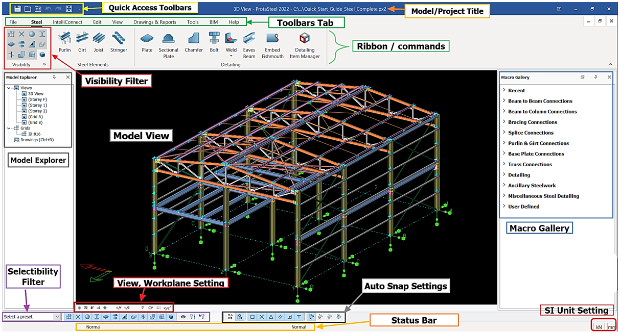
The various components of ProtaSteel user interface are as shown below:
The graphical user interface is composed of major parts as summarized as below:
Model Explorer
Model explorer is used to perform common tasks like opening and closing views, creating grids & loading the Drawing module. Model Explorer window can be docked to any side of the main window.
Views are created/imported from ProtaStructure under the "Views" collapsible folder in the Model Explorer pane in the left pane. By default, the views created are 3D view & plan view of each stories. Double-click on the desired view to access it.
Views
"Views" is a viewport that displays a part or the whole of the model.
When a new project is started, a general 3D view (a similar View Window is shown above) is created automatically. User can have any 3D view using mouse in animation mode (Right-click & Drag) or Reset Lookup button (F4) in Views Toolbar.
The graphical editor supports multiple windows; you can open as many windows as you desire. Modelling can be done both on the plan view as well as the 3D View.
Views are listed under the Views folder in the Explorer pane in the left pane. By default, the views created are 3D view & plan view of each storey. More views can be created using commands in View tab.
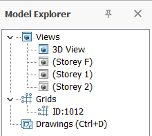
Double-click on the desired view to open it. Opened view will be shown in "Blue" icon while closed view has a "black" icon.
Double-click on Views (under Model Explorer) will open the "View Manager" where you can quickly :
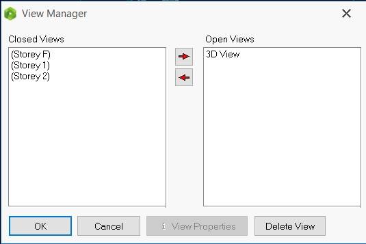
Open a view
Close a view
Delete a View
Display the View Properties
For more settings about views in ProtaSteel, please refer to this article: Views
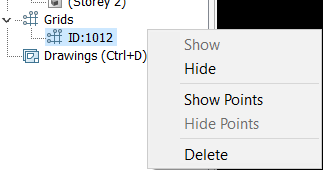
Grids
"Grids" is the axes imported from ProtaStructure. Double click on the grids ID will "Show" or "Hide" the grids. Alternatively, right click to perform the similar or more action.
Drawings (Ctrl+D)
Drawings (Ctrl+D) is drawing module that allows user to produce, modify and export drawings. Double click or press "Ctrl" + "D" (hotkey) to access the drawing module.
Visibility Filter
Each entity can be filtered visually by toggling on/off with single left click.

To inverse select the entity icon, hold "Shift" + double left click.
Macro Gallery
Macro Gallery consists all the steel connections creation tools, eg. gusset plate, fin plate, haunch, splice etc.

If you hover the mouse cursor over any icons, a tooltip will appear with detail explanation on how to use it.
By right-clicking on the macro icon, you can set the default parameters that will be used each time it is run.
Toolbars Tab & Commands
Toolbars tab give access to all general function of ProtaSteel.
Status Bar
Status bar, located at the bottom of the main window, displays information about:
- Current command
- Snap point type & Coordinates of snap point
- Spacing of grid snap points for moving elements.
SI Unit Setting
User can adjust the units of force and length in this setting.
View, Workspace Setting
View, Workspace Setting is a quick accessible tools to zoom, reset and rotate the view.
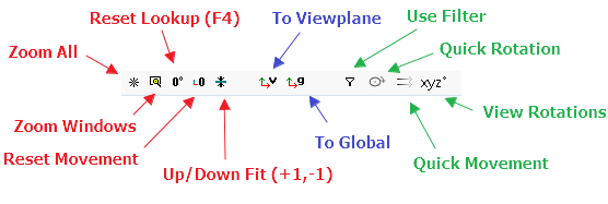
The controls involve:
Zoom All : Zoom to fit the visible of the full model into the active view.
Zoom Windows : Zoom to specific region by clicking on first corner and dragging to other corner.
Reset Lookup (F4) : Reset rotation of the view.
Reset Movement : Reset movement of the view and move the center of active view to workplane coordinate.
Up/ Down Fit (+1, -1) : Set upper and lower boundary of depth of the view for visibility to +1, -1 respectively. Click again will reset both boundary back to 0.
To Viewplane : Reset workplane to viewplane.
To Global : Reset workplane to global.
Use Filter : Active the filter set in Filter Option.
Quick Rotation : Speed up Rotation for "View Rotations"
Quick Movement : Speed up Movement for "View Rotations"
View Rotations : Rotate the model to given angle and ability to present a preferred angle.
Selectability Filter
The selectability of entity can be filtered by toggling on/off with single left click. Entity selectability that has toggled off will not be able to select or highlight in model view.
To inverse select the entity, hold "Shift" + double left click.
Auto Snap Setting
Auto Snap Setting provides conveniences to user when selecting point.
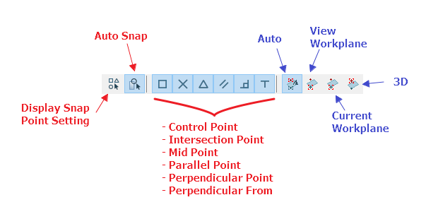
The controls involve:
- Display Snap Point Setting : To open Auto Snap Setting. Alternatively, press hotkey "Ctrl" +"B".
- Auto Snap : Toggle on to activate the auto snap. The auto snap will be based on selection method below:
- Control Point Intersection Point
- Mid Point
- Parallel Point
- Perpendicular Point
- Perpendicular From
By default, the auto snap point will be based on any workplane automatically. User can change here to select the snap point only set to below options:
- Auto
- View Workplane
- Current Workplane
- 3D