Working With Axes
Axis Properties
"Axis Properties” will be loaded by selecting the "Grid" icon in the "Modelling" ribbon or by choosing the "Properties" option in the shortcut menu (displayed by right-clicking the mouse) after the selection of an existing axis.
A new axis can be defined by specifying the necessary information in the given fields in the form and by specifying the endpoints of the axis line in the drawing area.
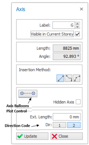
The "Axis Properties” form comprises the following fields:
- Single Segment
allows you to create a straight line axis by clicking on the start and end point of the axis.
- Multi-segment axis
enables you create a single axis with multiple segments of any shape.
(Left click to start create, press "Esc" key to roll-back, right click to end creation.) - Curve Axis
can be created by specifying the radius.

Defining a New Axis
Use the following steps to create a new axis:
- Click the "Grid" icon in the "Modelling" ribbon to load “Axis Properties”.
- Modify the data in the fields of the “Properties” form.
- For example, define the "Axis Label" or "Insertion Method".
- "Direction code" is no longer required to modify manually, it detects the direction automatically when the axis is drew.
- Click the left mouse button in the first point, then left-click on second point and release the button. The new axis will appear.
- " Length " and " Angle " can be used to control the direction and length of the dragged grid during insertion.
- In order to activate these options and to constrain cursor movement to the horizontal or vertical directions (or relative to the angle defined) hold down the Ctrl key while dragging to the second point and release the key after left mouse button.
- You can also generate parallel axes from an existing axis.
- To do this, first select an existing axis and right-click the mouse to open the shortcut menu.
- Then choose " Offset Axis " option to activate the related form for the generation.
- If the " Axis Properties " form is active during the selection of an axis, you can activate the form for generation also by choosing the " Offset Axis " in the " Modify " toolbar.
- When the related form appears on the screen, enter values in the " Offset from Previous " field to specify the offset distance from the existing axis.
- The new axis will be placed at the given offset from the previous axis on the side picked.
- To define another label, modify the " Axis " field before clicking the offset side.

- During the rubberband operation, the length (L) and local angle will displayed. In addition, the relative distance ∆x & ∆y with respect to the local UCS will also be shown.
- Press F2 to enable input of the length (L) of axis via Dynamic Input System (DIS)
- Press TAB to cycle to the next input of angle
- If a value is entered in the textbox, the related parameter will be locked. You can unlock by pressing ESC or pressing the lock icon at the right of the text box.
- In either of the text boxes, you can use shortcut notation Length<Angle or DeltaX, DeltaY (without the need to switch by TAB.)

Defining a Curved Axis
The method for defining Curved Axes is as follows:
- Press the “Grid” icon located in the "Modelling" ribbon to load the “Axis Properties” form. Enter the Axis Label in the “Label” field.
- Choosing the “Curve Axis Insertion” from the insertion method, left-click to define the start point and left-click to define end point :
- First and second points defined in this way will be the “I” and “J” points of the axis respectively.
- Move the mouse cursor to define offset of the curve and click to confirm it.
- Alternatively, press “F2” to define the chord offset of the axis. Note that you can use negative values in the dialog.
- After editing the fields in this dialog, press the “ENTER” button to complete the definition of the curved axis.
- The axis will be drawn on the screen accordingly.
Orthogonal Axis Generator
Grid Insertion
Includes the “Reference Point” and “Insertion Angle” fields. X and Y coordinates of the previously picked reference point is automatically given in the Reference Point fields. These values may be changed to specify a new reference point.
Insertion angle is the rotation angle of the axes to be generated in both directions (“1” and “2”) in anti-clockwise direction relative to their default directions.
Direction-1 Axes / Direction-2 Axes
Comprises the “Axis Label”, “Step”, “Axis Spacing(s)” and “Axis Extension Length” fields to be filled for the dir-1/dir-2 axes to be generated.
| Function | Description |
| Axis Label | Label of the first axis in this direction. Dir-1 or horizontal axes label will start from bottom to top. Dir-2 or vertical axes label will start from left to right. |
| Axis Spacing(s) | Spacing between each axes at the same direction. You can delimit with comma character in unequal spacings used. Repeating spacings may be entered using " * " as multiplier, provided that spacing to be written before number of spans. (Ie. 5000, 2000*3, 4000) |
| Step | Axis label increment to be used for generating the successive labels. |
| Axis Extension Length | Distance that axes to be extended beyond the intersections. |

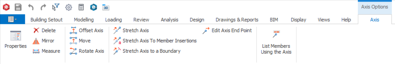
Axis Shortcut Menu & Axis Option Tab
- "Axis Option" Ribbon tab
- Shortcut menu (displayed by right-clicking the mouse)
- "Move" & "Stretch Axis" function works with multiple axes selected
- “Rotate Axis ”, "Offset Axis". "Edit Axis End Point" only works with single axis selected
Moving an Axis
- Select one or more axis.
- Select / Click "Move Axis" in the axis shortcut menu / Axis Option tab.
- Move the mouse cursor & preview of axis will be shown
- Press “F2” to manually input value :
- Input the parallel distance to be moved
- Alternatively, input [delta x] , [delta y] values
- Press "Enter" & axis will be moved
Stretching an Axis
- Select an axis or a parallel array of axes. Select the "Stretch Axis" option in the axis shortcut menu or in the ribbon tab.
- Left click on any point near to the end that wish to stretch and a ruler showing distance will appears as you move your cursor away from the first point.
- Move mouse cursor & left click again to complete the stretching. Alternatively, use "F2" to key in the distance value and press "Enter".
- The direction of axis line(s) will not be altered by the stretch function. The selected axis line(s) will be stretched by the absolute length of the dragging line in XY plane.
Edit Axis End Point
- Select a axis. Click "Edit Axis End Point" option.
- Define the new axis end point by picking one point.
- The closer end point of the selected axis will be changed to the point you picked.
Stretch Axis to Member Insertions
- Select one or more axes and select “Stretch Axis to Member Insertions” option. In this case, the function will be applied to selected axes (or multiple axes) in the model.
- The “Stretch Axes to Member Insertions” dialog will be loaded.
- The axes will be stretched automatically based on the settings when the “OK” button is pressed.
The available options in this dialog:
- Consider Axis Intersections As Well
If you have an orthogonal axis grid, you can check this option if you like to consider not only the member insertion points but the axis intersections as well.
- Shrink Only
If you check this option, axes will only be shortened during this operation.
- Axis Extension Length
The axes will be extended further away from the outer member insertion (or axis intersection, if “Consider Axis Intersections As Well” is checked) by the amount entered in this field.
- Apply to Selected or All Axes
By default, the function will only be applied to selected axes if initiated by the shortcut menu. If you check the “Apply to All Axes” option, the operation will be applied to all the axes in the model.
Stretch Axis to a Boundary
- Select one or more axes. Click “Stretch Axis to a Boundary” option.
- Define the boundary by picking two points to stretch the Selected Axes.
- The closer ends of the selected axes will be extended or shortened to meet the boundary.
- The process will be aborted if you fail to define a proper boundary.
Rotating an Axis
- Select one axis only (option does not work with multiple axes)
- Click “Rotate Axis” option.
- Click the rotation base point in the drawing area.
- Rotation base point can be picked by using one of the object-snap modes.
- For example, if you want to pick the intersection of two axes as rotation base point, press the "Intersection" button in the Osnap Form, position the square on the cursor close to the desired intersection and click the left mouse button.
- By pressing “F2” you can enter the new axis angle (measured counter-clockwise from the horizontal) to the "Angle" field > Press “Enter”
- Press "Enter" again & the axis will be rotated.
Create Frame View
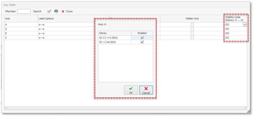
Axis Table
Changing Visibility for Multiple Grids
Guidelines when creating grids / axes
- Try to avoid axis that are very close together
Since member insertion is based on axes intersection, having too many axis that are too close together may result in picking the wrong intersection of axes when creating members. - Use as few axes as possible
For the same reason above, model only the necessary axes. Note it is the structural behavior that is important, hence small architectural offsets discrepancies will have negligible difference. For example it would be unreasonable to model 2 parallel axes with only 30mm between them – where a single axis would suffice.
- Keep axis short and localized to the place where it is used
For the same reason above, this is to avoid too many axes intersection. Note that you automatically shorten axes by selecting axes > Right-click > "Stretch Axis to Member Insertion. - Set Axes to Ghost to clear the clutter in the view
You can set an axis a ghost by unchecking "Visible in Current Storey" in the Axis Property. Once set, these axes will be shown as light grey, which can be completely turned of by deactivating "Ghost Axes" in Layers tab (Display Ribbon).
- Perform ‘Building Model Check’ progressively
Building Model Check will check for commons errors for axes. For more information of building model check can refer to this article: Building Model Check