Working With Columns
Defining a New Column
Before inserting a column member its reference axes must be defined.
Column can only be inserted on insertion point defined by intersection of 2 axes.
- Display the storey level in the drawing area which will contain the top of the column.
- To create concrete column, pick “Column” from the “Modelling” ribbon at RC Members section.
- To create steel column, pick “Column” from the “Modelling” at Steel Members section.
- Edit the fields in the "Column Properties" form. For example, enter the column label in the "Label" field (max. 8 characters) to modify the section dimensions and eccentricities.
- To insert the column, click on the required reference point in the either the plan view drawing area or the 3D view. You have to pick an axis intersection as the insertion point.
- Labels of the reference axes will be shown in “Top” and “Bot” fields on “Column Properties” form.
- The same axes intersections will be written in these fields when the column is first defined. In this case, column will be placed vertically along the storey levels.
- In order to define a column that is inclined along the storey levels, “Top” and “Bot” fields must be changed later on. Changing the insertion axes of a column is explained under “Insertion Axes” title of this section.
- Multiple columns with the same properties can be inserted at the same time by dragging a window enclosing multiple intersection of axes. Columns will be inserted at every axes intersection within the window.
Editing an Existing Column
- Select an existing column.
- Right-click and select the “Properties” menu option.
- Alternatively, double left-click on a column to bring out the Properties menu.
- Modify the fields in the "Column Properties" form.
- Press the "Update" button in the “Properties” form.
Right-clicking on any one of the “b1”, “b2”, “e1”, or “e2” fields will load a list of commonly used values that may facilitate data entry.
You can repeat this process on as many members as you wish. One member at a time can be edited by this method.
Editing Multiple Columns
- Multiple select columns to be edit > Right-Click > Properties
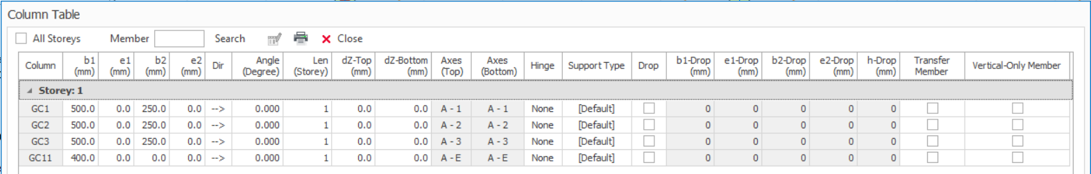
- Column Table dialog will be shown where you can display & edit properties in a group
- Right-Click anywhere in the modelling view
- Select "Member Tables" > Column Tables
- Column Table will show all columns in the active Storey
 Refer to this article for details : Display and Edit Member Properties
Update Column End Conditions
To change the end conditions for multiple columns at the same time:
- Select the existing column(s).
- Right-click and select “Update Column End Conditions”.
- Choose the required end conditions, i.e. Fix or Hinge
- Press the "Apply to Selected Columns”, “Apply to All Columns in Current Storey" or "Apply to All Columns in the Model" as required.
Column Properties
The “Column Properties” form can also be accessed after selecting an existing column and then by right-clicking and choosing the “Properties” option in the shortcut menu.
When the “Column Properties” form is open, right clicking on a new column member in plan window and selecting the “Select and Load Properties” option in the shortcut menu will load the properties of the new member in the same window.
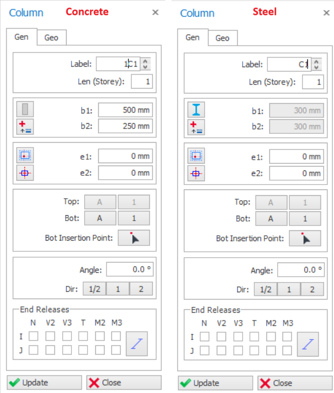
Label
The label that will identify the column can be entered in this field. This field (after formatted to be a proper label) is limited to 8 characters. A text control spin button exists to the right of the label field to facilitate the creation of successive label text.
As in all member types, column member labels will be listed in the “Structure Tree” under the related storey heading. This list can be used to select a member by label.
Repeating member labels is not permitted in a building. During the insertion of members the program will sound an alarm and a warning message will appear in the status bar if a repeating member label is detected.
Len (Length Storey)
Enter the number of storeys the column spans. Generally, every column spans one storey in building type structures. If the column span more than one storey, the number of storeys can be defined in this field.
For example, if a column in the 4th storey spans to the 2nd storey top level, this means that the column will exist along 4th and 3rd storeys. Therefore, "2" must appear in the "Len (Storey)" field.

RC Column Dimensions (b1, b2)
"b2" dimension must be zero to define a circular column. When “b2” is zero, "b1" will be the diameter of the circular column.
is limit to the ratio of the dimension (b2/b1) of the columns according to
selected code of practice. If the ratio is exceeded, it must be modelled as a
wall instead for column.
dimension exceeds 4 times the smaller dimension should be designed as wall, as
per BS8110-1997 (Cl.1.3.4.1).
"e1" and "e2" fields define the eccentricities of the column from the insertion axes along direction 1 and 2, respectively.
Column Insertion Options Button
A set of column insertion option buttons are provided for facilitating the definition of “e1” and “e2” fields.
|
| After setting the dimensions of a column, you can easily set the column eccentricities by pressing the “Column Insertion Options” button. After pressing this button a window will appear displaying “Eccentricity Option Buttons”. |
Choosing one of the options available in the “Eccentricity Option Buttons” will automatically redefine the “e1” and “e2” fields.
It should be noted that the eccentricities of the column defined here will not modify the location of the actual analytical frame member used in the analysis model. The frame member will be located on the insertion point of the column.
A positive value entered in “Eccentricity (a)” field is used to shift the insertion point of the column in both "1" and "2" directions. The formulation used can be viewed in the tooltip of relevant buttons.
Alternatively, you can control the “e1” and “e2” values using the direction keys of your keyboard.
- Then, when you press left or right keys, the “e1” property, when you press up or down keys, the “e2” property will be modified and the column is displaced.
- The eccentricity step value can be set using the “Member Section Eccentricity Step” value in Settings Center > ProtaStructure Environment
Column Anchor Point
A set of column anchor option buttons are provided to anchor a specific point on its section.
|
| After you anchored a point on column section, when the section size is changed, the member is automatically resized with reference to the anchor point. |
To assign Anchor point via Column Properties window:
- Select a column, right-click and choose "Properties".
- Click on the Anchor icon and choose the desired anchor point.
To assign Anchor point via right-click dialog:
- Select a column.
- Right-click select "Column Section Anchor Point", choose the desired anchor point.
Alternatively, select the column:
- Press CTRL + SHIFT + Arrow keys to set anchors to corners automatically
- Press CTRL + Arrow keys to flush the member to grids.
Insertion Axes
All structural members are inserted based on axis intersections as an insertion reference. At least two axes must intersect at every insertion point.
Labels of the reference axes will be displayed in “Top” and “Bot” fields on “Column Properties” form. Same axes intersections will be written in these fields when the column is first defined. In this case column will be placed vertically along the storey levels.
 . Refer to this article of slanting or inclined column : Define Slanting/Sloping Column.
Column Orientation
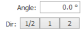
Column orientation can be controlled "Angle" input. Angle is always measured horizontal, anti-clockwise.
- When "1" is pressed, "b1" dimension of the column will be set parallel to the direction-1 insertion axis that appears in the "Axes" fields. "b2" dimension will be perpendicular to this direction.
- When "2" is pressed, "b2" dimension of the column will be set parallel to the direction-2 insertion axis that appears in the "Axes" fields. "b1" dimension will be perpendicular to this direction.
- When "1/2" is pressed, then dimension of the column will be parallel to both direction 1 & 2 insertion axes respectively.
Column End-Condition Options (Fix / Hinge)
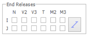

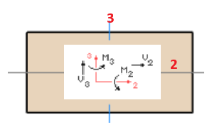
- N releases the internal axial force
- V2 releases the shear along axis 2
- V3 releases the shear along axis 3
- M2 releases the moment about axis 2
- M3 releases the moment about asix 3
Section Manager
Column section manager and material can be accessed in “Edit Section / Material” by either :
- Click "Section Manager" icon

 in column Properties menu
 - Select a column > Right-Click > select "Edit Section / Material"
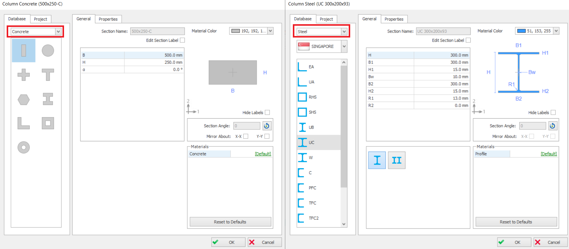
- Concrete : If concrete is chosen, various types pre-defined shapes such as "L", "T", "I" can be selected.
- Steel : If Steel is chosen, then various country section database can be chosen such as Euro, Singapore, Japan, Chine, etc.
- Built Up Steel : Can be used to enter non-standard steel sections.
- Cold Formed : Cold formed sections usually used for roof, e.g. "Z" sections
- Composite : Steel column encased in concrete (without / without Steel Casing)
- The section name, dimensions. display color & Materials can be changed in “General” tab.
- The moment of inertia, section area and other properties can be reviewed in the “Properties” tab.
General tab
Section dimensions input fields will be shown and can be edited.
- To change from default, you can click on [Default] to change the material.
- However, we advise you do not change the default as material are best set in master Materials dialog (in "Building Setout" ribbon). This is more efficient that trying to set each column material one by one.
Properties tab
The section properties tab shows all the auto-calculated section properties of the column.
“A” is the gross area of the section
“Shear Area” is used for the calculation of shear deformations and is calculated automatically as "5/6" times the axial area of the section.
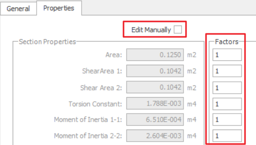

- Under Factors, input the ratio, example 1 = 100%, 0.5 = 50%
- Check "Edit Manually" & manually enter values. Be warned that this will de-link the auto-calculation of section properties, e.g. when column sizes change.
Column Geometry tab
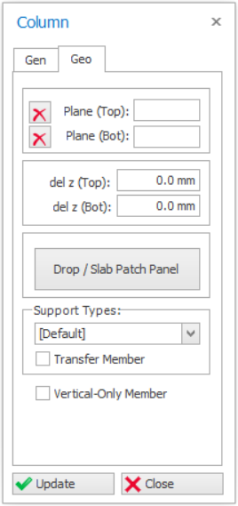
Plane (Top) & (Bot)
 .
.
del z (Top) & (Bot)
- The top node of the column is the same as the top of the storey ST01 level – i.e. del z (Top) = 0mm
- The bottom node is the same as the top of the below storey ST00 level – i.e. del z (Bot) = 0mm.
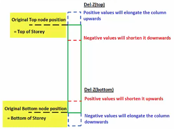
- Del z (Top) : Positive value will elongate the column upwards, vice versa
- Del z (Bot) : Positive value will shorten the column upwards, vice versa.
If "Plane" is used to define the column, the delta z value will automatically be calculated based on plane elevation & these fields will be deactivated.
Drop / Slab Patch Panel
In Flat Slab type floor systems (no beams), a drop panel can be inserted on top of the columns in order to increase punching resistance.

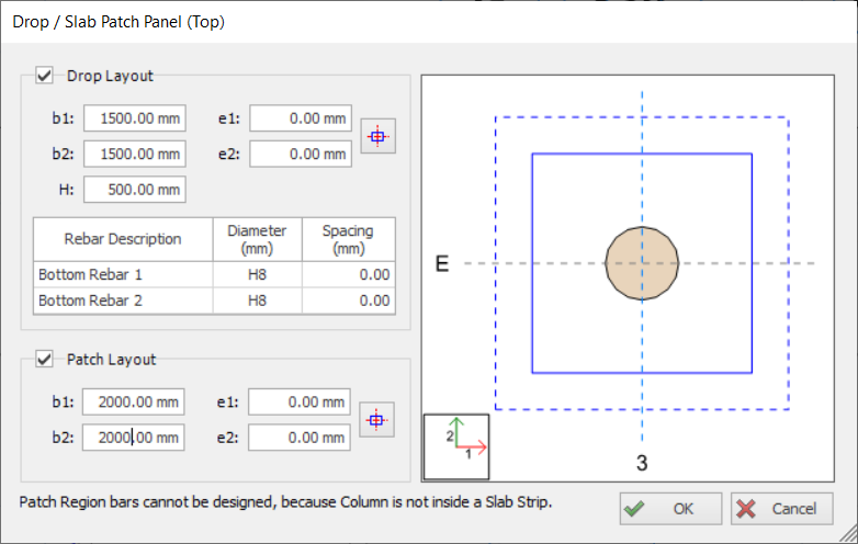
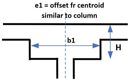
- Dimensions and Eccentricities of the Drop Panel can be adjusted using “b1”, “b2”, “e1” and “e2” data fields. Definition of these parameters are identical with column dimension and eccentricity parameters.
- In order to locate the drop panel just to center the column, press “Center” button
 . “e1” and “e2” values will automatically be determined according to the column size.
 - "H" field is the total depth of the Drop Panel, measured from top of the flat slab. Hence, the value must be more than the slab thickness.
- Dimensions and Eccentricities of the Drop Panel can be adjusted using “b1”, “b2”, “e1” and “e2” data fields
- In order to locate the drop panel just to center the column, press “Center” button . “e1” and “e2” values will automatically be determined according to the column size.
Kindly read this article for further details on flat slab design using drop & slab patch panels : Flat Slab and Raft Design with Slab Patch PanelsSupport Types
You can review or change the Support Type for the bottom Node of a column :
- [Default] – For all columns & walls created in ST01, a default fixed support (restrains in all six degree of freedom (DOF) will always be created & assigned automatically, as ST01 is the ground floor
- For all columns & walls created in ST02 and above, the [Default] option means it is free to move (not restrained) and will automatically be supported by elements modelled below it.
- [None] means the column or wall be free to move in 3D. This option should not be used, as it ignore any elements modelled at the column bottom node.
- If there are other supported types created via Support Type function – they will be listed & selectable.
Transfer Member
Refer to this article for details : How to model a Transfer Beam supporting discontinuous columns and wallsVertical only Member
Update Button
Whenever you make new specifications in one of the fields in “Column Properties” form for an existing column member, press the “Update” button in order to display the changes in the plan window.
Close Button
Pressing the “Close” button will close the “Column Properties” form and return back to “Select Mode”.
Column/Wall Shortcut Menu
A shortcut menu for a single column selection includes “Polyline Column Editor”, “Column Reinforcement Design”, “Column Steel Details” and “Column Punching Check” options specific to a column member. These options will be omitted from the shortcut menu when multiple columns are selected.
“Delete”, “Mirror Elements” and “Properties” options are default options in shortcut menus for all member types. All the options provided in a column shortcut menu may also be accessed by using the pulldowns.