Working With Walls
Defining a New Wall
Before inserting a wall member its reference axes must be defined.
- Display the storey level in the drawing area which will contain the top of the wall.
- Press the “Wall” button located in the "Modelling" ribbon > Wall "Properties" dialog will appear.
- Edit the fields in the "Wall Properties" form. For example, enter the Wall Label in the "Label" field (max. 11 characters) to modify the section dimensions and eccentricities.
- To insert the wall, pick two axes intersections to insert the wall, in view drawing area, or the 3D view.
Wall Shortcut Menu
- The Wall ribbon will appear with at the top containing all relevant commands
- Alternatively, right-click anywhere in the modelling view will also expose the same shortcut menu.
- Command functions for single wall selection includes “Polyline Wall Editor”, “Section Design”, “Elevation Drawing” and “Punching Check”. These options will be omitted from the shortcut menu when multiple walls are selected.
- “Delete”, “Mirror Elements” and “Properties” options are default options in shortcut menus for all member types.
Editing an Existing Wall
In order to edit an existing wall:
- Select an existing wall.
- Right-click and select “Properties” menu option.
- Alternatively, double left-click on a wall to bring out the Properties menu.
- Modify the fields such as "b" and "e” in the "Wall Properties" form.
- Press the "Update" button in the “Properties” form or Right-click and select “Update” option in the Shortcut Menu.
Right-clicking on any one of the “b”, “e”, “Ext. I”, or “Ext. J” fields will load a list of commonly used values that may facilitate data entry.
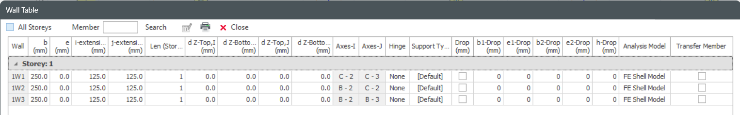
You can repeat this process on as many members as you wish. One member at a time can be edited by this method. If you want to update several columns at once, you can use "Wall Table" in the "Member" menu. The “Wall Table” form can also be reached from the “Member Tables” option in the shortcut menu.
Editing Multiple Walls
- Multiple select walls to be edit > Right-Click > Properties
- Wall Table dialog will be shown where you can display & edit properties in a group
- Right-Click anywhere in the modelling view
- Select "Member Tables" > Wall Table
- Wall Table will show all walls in the active Storey
 Refer to this article for details : Display and Edit Member Properties
Wall Properties
The “Wall Properties” form can also be accessed after selecting an existing wall and then by right-clicking and choosing the “Properties” option in the shortcut menu.
When the “Wall Properties” form is open, right clicking a new Wall member and selecting the “Select and Load Properties” option in the shortcut menu will load the properties of the new member in the same window.
The “Wall Properties” form comprises 2 pages named as “Gen” = General & "Geo" = Geometry. You can shift between pages by pressing the related tab heading.
The General tab consists of the following fields / options :
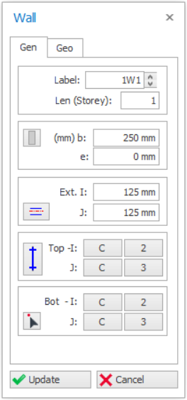
Label
The wall label can be entered in this field. This field (after formatting) is limited to 11 characters. A text control spin button exists to the right of the label field to facilitate the creation of successive label text.
Repeating member labels is not permitted in a building. During the insertion of members the program will sound an alarm and a warning message will appear in the status bar if a repeating member label is detected.
Len (Length Storey)
Enter the number of storeys the wall spans. Generally, every wall spans one storey in building type structures. If the wall span more than one storey, the number of storeys can be defined in this field.
For example, if a wall in the 4th storey spans to the 2nd storey top level, this means that the wall will exist along 4th and 3rd storeys. Therefore, "2" must appear in the "Len (Storey)" field.

"b" is the thickness of the wall, which is the section dimension along its minor direction.
is minimum limit to the ratio of the dimension (length/b) of walls according to
selected code of practice. If the minimum ratio is not satisfied, it should be
modelled as a column instead of a short wall.
example, if British Code is selected, wall whose length that is less 4 times its thickness
(b) would be designed as column, as per BS8110-1997 (Cl.1.3.4.1).
The eccentricity of the wall along its minor direction is defined by the field "e" measured as a distance between the insertion axis and the centreline of wall having a left I-end and a right J-end.
"e" value cannot be greater than section width/2 or smaller than the –width/2.
Wall Insertion Options Button
 Insertion Options | After setting the dimensions of a wall, you can easily set the column eccentricities by pressing the “Wall Insertion Options” button. After pressing this button a window will appear displaying “Eccentricity Option Buttons”. |
Choosing one of the options available in the “Eccentricity Option Buttons” will automatically redefine the “e” field.
It should be noted that the eccentricities of the wall defined here will not modify the location of the actual analytical frame member used in the analysis model. The frame member will be located on the insertion point of the wall.
Alternatively, you can control the “e” value using the direction keys of your keyboard.
- Select a wall and load the “Properties” dialog.
- When you press left or right keys, the “e” property will be modified and the wall is displaced.
- The eccentricity step value can be set using the “Member Section Eccentricity Step” value in Settings Center > ProtaStructure Environment
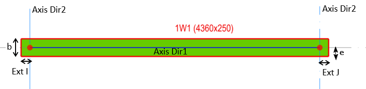
Wall Extensions (I, J)

Insertion Axes
All structural members are inserted based on axis intersections as an insertion reference. At least two axes must intersect at every insertion point.
The simplest method for defining the insertion axes of wall elements is selecting two axes intersections in the drawing area. Left click to select the first point and then left click to select the second point.
Following rules apply for the insertion of Walls:
- Insertion points can be clicked in any preferred direction along the insertion axis.
- The defined "I" and J" points will be swapped automatically when necessary based on the lower left point priority method.
- At least one common axis must exist among the two intersections. This common axis is termed as the "Insertion Axis" of the Wall.
Labels of the axes that reference the “I” and “J” ends of the wall will be displayed in “Top” and “Bot” fields in the “Wall Properties” form. Identical axis intersections will be written in these fields when the wall is first defined. In this case wall will be placed vertically between the storey levels.
A vertical wall can be changed to inclined or slanting by changing the bottom insertion axis :
- Click "Bottom Insertion Point icon

- Pick the new longitudinal axis line on plan
- Click "Update" & the wall will be inclined (Review 3D view)
 For illustration, you can refer to similar article for slanting column : How to model slanting / inclined column.
Wall End-Condition Options (Fix / Hinge)
|
| You can use the "Wall End-Condition (Fixed/Hinged)" button to release moments of top, bottom or both ends to assume pinned-end condition. By successively pressing this button you can follow which end becomes hinged. Click "Update" icon to take effect |
 Any hinge setting will only apply for "Mid-Pier" wall analysis type and not "FE Shell". "FE Shell" wall will always fixed at top and bottom nodes.
Wall Section Manager
- Click "Section Manager" icon
 in wall Properties menu
 - Select a wall > Right-Click > select "Edit Section / Material"
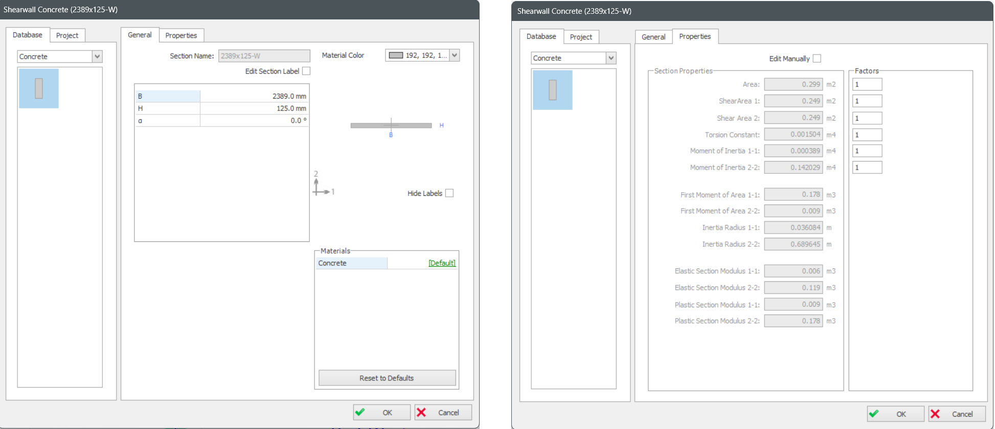
General tab
Section dimensions input fields will be shown.
- To change from default, you can click on [Default] to change the material.
- However, we advise you do not change the default as material are best set in master Materials dialog (in "Building Setout" ribbon). This is more efficient that trying to set each wall material one by one.
Properties tab
The section properties tab shows all the auto-calculated section properties of the wall.
“A” is the gross area of the section.
“Shear Area” is used for the calculation of shear deformations and is calculated automatically as "5/6" times the axial area of the section.
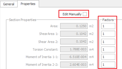

- Under Factors, input the ratio; example 1 = 100%, 0.5 = 50%
- Check "Edit Manually" & manually enter values. Be warned that this will de-link the auto-calculation of section properties, e.g. when column sizes change.
Wall Geometry tab
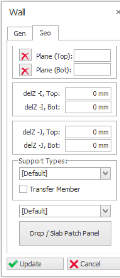
Plane (Top) & (Bot)
 .
.
del z (Top) & (Bot)
- The top I & J nodes of the wall is the same as the top of the storey ST01 level – i.e. del z (Top) = 0mm
- The bottom I & J nodes is the same as the top of the below storey ST00 level – i.e. del z (Bot) = 0mm.
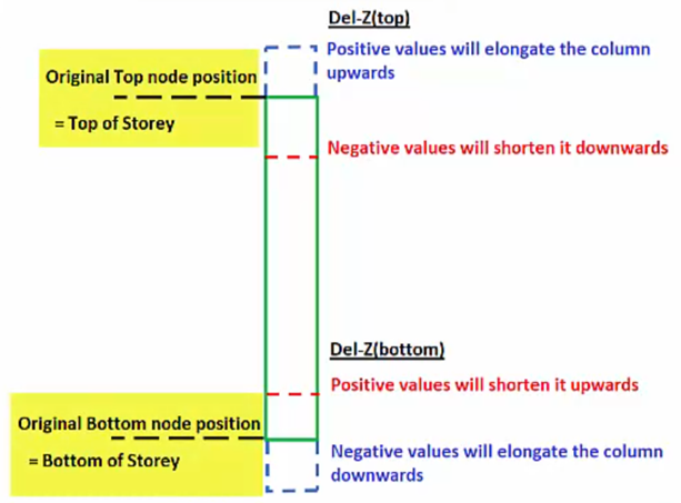
- Del z (I & J) (Top) : Positive value will elongate the wall upwards, vice versa
- Del z (I & J) (Bot) : Positive value will shorten the wall upwards, vice versa.
If "Plane" is used to define the wall, the delta z value will automatically be calculated based on plane elevation & these fields will be deactivated.
Support Types
You can review or change the Support Type for the bottom Node of a column :
- [Default] – For all columns & walls created in ST01, a default fixed support (restrains in all six degree of freedom (DOF) will always be created & assigned automatically, as ST01 is the ground floor
- For all columns & walls created in ST02 and above, the [Default] option means it is free to move (not restrained) and will automatically be supported by elements modelled below it.
- [None] means the column or wall be free to move in 3D. This option should not be used, as it ignore any elements modelled at the column bottom node.
- If there are other supported types created via Support Type function – they will be listed & selectable.
Transfer Member
Refer to this article for details : How to model a Transfer Beam supporting discontinuous columns and wallsWall Model Type
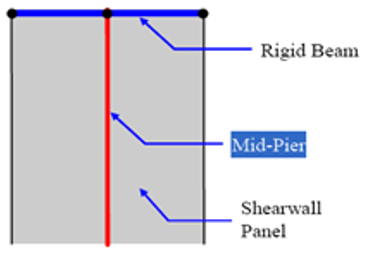
- Mid-Pier Model [Default]
This utilizes a single column (mid-pier) at the center of the wall with rigid beam at the top of the wall.
- Rigid beam is auto-created to support other members.
- Deflection is constant along the entire rigid beam length.
- Analysis time is efficient.
- Suitable for normal shear walls that starts from foundation to superstructure.
- Finite Elements Shell Model
Entire wall is meshed as shell elements.
- Variation of stresses along the wall length & height can be captured.
- Deflection can be different along the wall length.
- Suitable & more accurate for transfer wall supported by transfer beam. Example refer to : How to model a Transfer Beam
- Suggested mesh size is approximated storey height divided by 4.
- Merged shear walls are automatically meshed.
- Basement Wall (Meshed)
- This is specifically for seismic analysis & design of basement walls; where special consideration of the participation of the basements mass in the dynamic analysis is varied.
- These results are run concurrently & combined in accordance with the relevant seismic code.
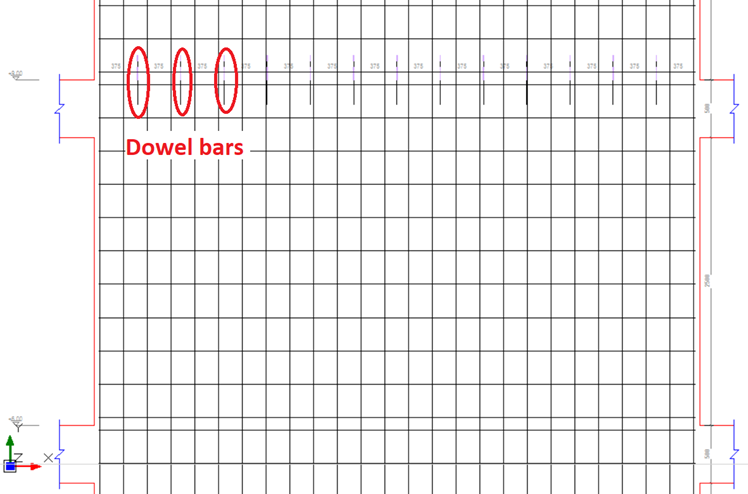
- Retrofit Wall (Shell / Mid-Pier)
- A retrofit shear wall is similar to a RC regular shear wall, except that additional “Anchor (dowel bar)” are added for seismic strengthening.
- There will be an additional “Anchor (dowel bar) Design” button in the Interactive Column Design Interface, which can be designed for retrofit.
- These walls are recognized by ProtaDetail & special dowel detailing can be produced (as shown below in a shear wall elevation detail).
Drop / Slab Patch Panel
In Flat Slab type floor systems (no beams), a drop panel can be inserted on top of the wall in order to increase punching resistance.
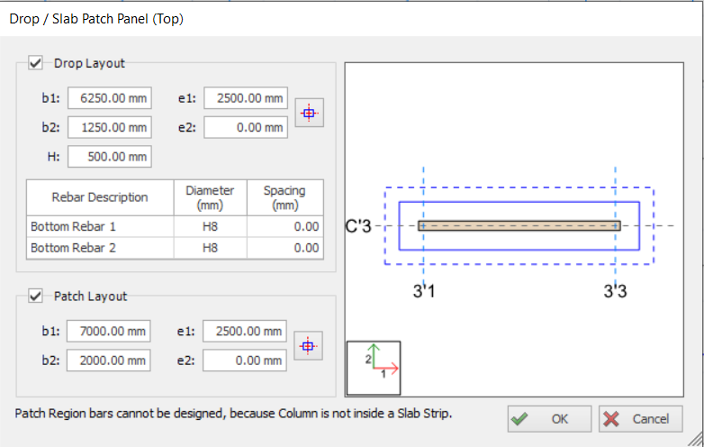
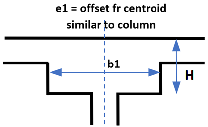
- Dimensions and Eccentricities of the Drop Panel can be adjusted using “b1”, “b2”, “e1” and “e2” data fields. Definition of these parameters are identical with wall dimension and eccentricity parameters.
- In order to locate the drop panel just to center the wall, press “Center” button
 . “e1” and “e2” values will automatically be determined according to the wall size.
 - "H" field is the total depth of the Drop Panel, measured from top of the flat slab. Hence, the value must be more than the slab thickness.
- Dimensions and Eccentricities of the Drop Panel can be adjusted using “b1”, “b2”, “e1” and “e2” data fields
- In order to locate the drop panel just to center the wall, press “Center” button . “e1” and “e2” values will automatically be determined according to the wall size.
Kindly read this article for further details on flat slab design using drop & slab patch panels : Flat Slab and Raft Design with Slab Patch PanelsUpdate Button
Whenever you make new specifications in one of the fields in “Wall Properties” form for an existing column member, press the “Update” button in order to display the changes in the plan window.
Close Button
Pressing the “Close” button will close the “Wall Properties” form and return back to “Select Mode”.
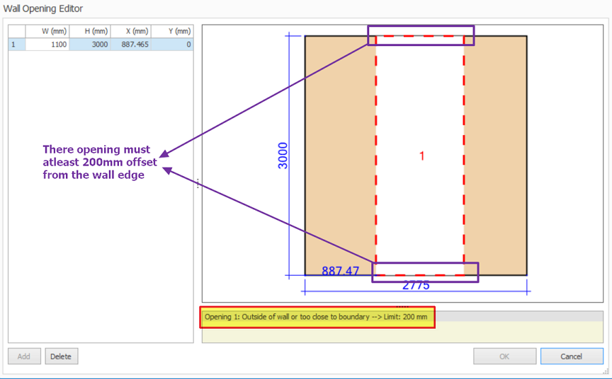
Wall Openings
Multiple openings can be defined for shear walls / core walls using "Wall Opening Editor". Rectangular or square opening can be accurately positioned to consider door opening for example.
Steps:-
- Select a shearwall, right-click and select "Wall Opening Editor".
- "Wall Opening Editor" dialog will appear.
- Click Add/ Delete buttons to insert/ delete openings.
- User can select the openings on the drawing or on the table.
- User can change Width, Height, and Position of the openings on the table.
Before analysis, ensure that the wall model is set to FE Shell Model :
- Select a wall > Right-click and select Properties > Geo tab > Wall Model Type > Pick FE Shell Model (only this wall will be meshed) OR
- Go to Building Analysis menu > Models Options > ShearWall Model > check Finite Element Shell Model (all walls in the model will be meshed)
- Wall opening will be only considered when using FE shell wall. (Change in Wall Properties > "Geo" tab)
- Design of wall will not taken into account of wall opening. Thus, wall with opening will be designed as normal wall.
- Reduction of section area due to wall openings will NOT be considered in the design of the walls and only consider in analysis when meshing the walls. The analysis results of localized and distributed forces that are experienced by the walls will be represented as contours.
- In elevation detail, trimmer bars will be provided as good practice but these are not designed for specifically to any code of practice.
As such, currently this function is more useful for small opening such as window opening.
Merged Shear Walls / Core Walls
Multiple shear wall panels can be selected and merged into a single core wall. This allows the shear wall to be analyzed, designed and detailed as single integrated entity, increasing efficiency & productivity. The steps are :
- Multiple select connecting shearwalls
- At the top wall ribbon select "Merge Vertical Members"
- Alternatively, Right-click > Select "Merge Vertical Members"
- Separate wall panels will be merged into single core wall
- If there are any openings on panels, they will be reflected on the core wall as well.
- The label of the longest wall will be used.
- All the panels are also kept in the wall records so walls can be unmerged by choosing "Unmerge Vertical Members"
We recommended for initial or preliminary stage, shearwalls should not be merged. The reasons are :
- For unmerged single panel walls, the wall design is fully automated. The design automatically selects the size, number and position of bars.
- For merged walls, the design is partially automated. The rebars numbers & position must be manually defined first. The design only chooses the rebar sizes to achieve pass status.
- Refer this article on how to define rebars for merged walls : Define Merged Wall/Irregular column Reinforcement in Polyline Column Editor
- If single panel walls (unmerged) fails in design, it is unlikely that it will pass when merged, as the design forces are essentially the same.
- As such, it’s logical to model & analyze shearwalls as separate panels first (i.e. unmerged) > design the walls and ensure all the walls passes.
- Then if desired, merge the walls & define bars according to the initial design and proceed to re-design the walls.